Symmetrical fluidization coater for high capacity manufacturing

Inactive Publication Date: 2002-10-08
GENENCOR INT INC
View PDF5 Cites 7 Cited by
  • Summary
  • Abstract
  • Description
  • Claims
  • Application Information

AI Technical Summary

Benefits of technology

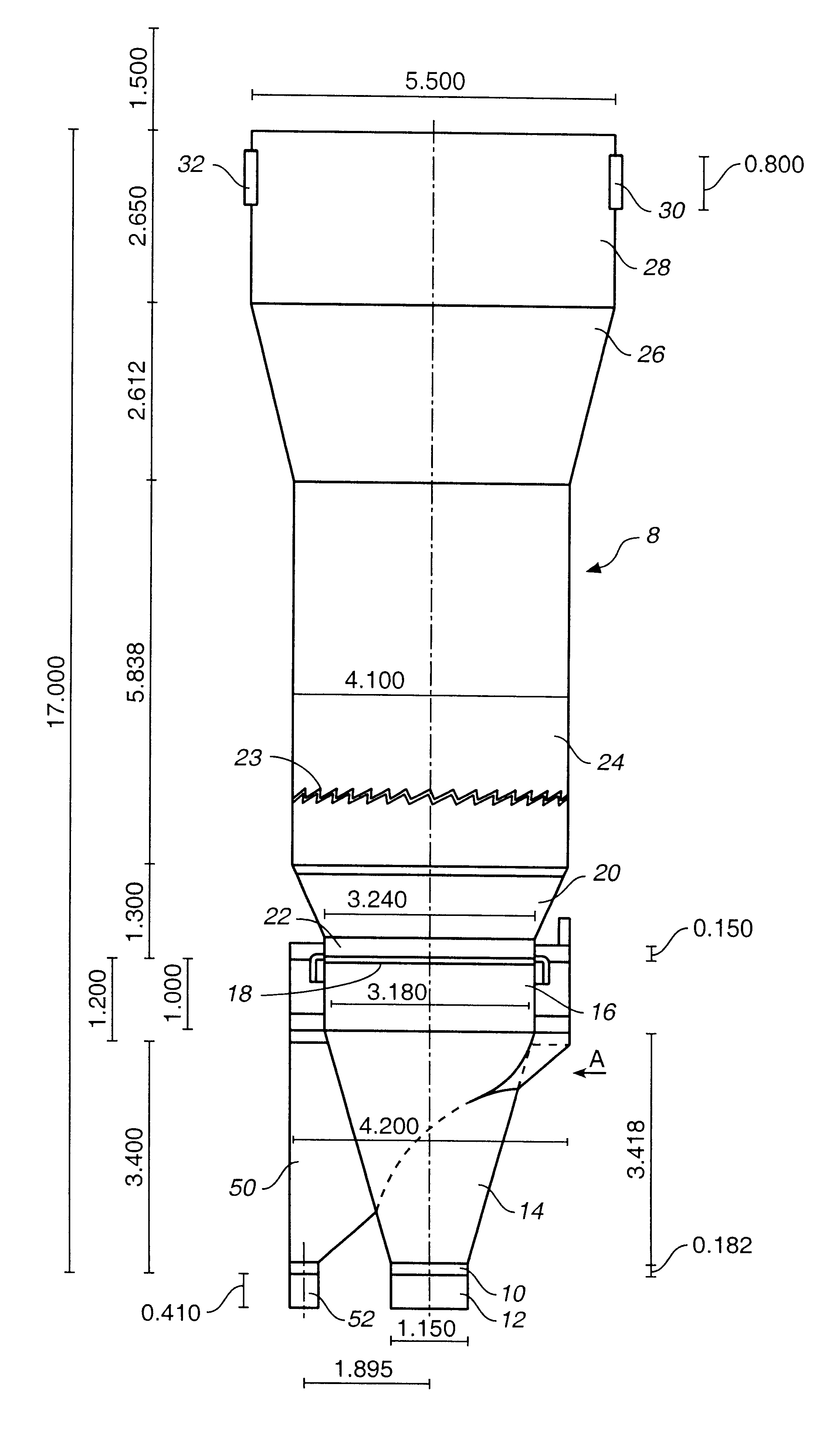
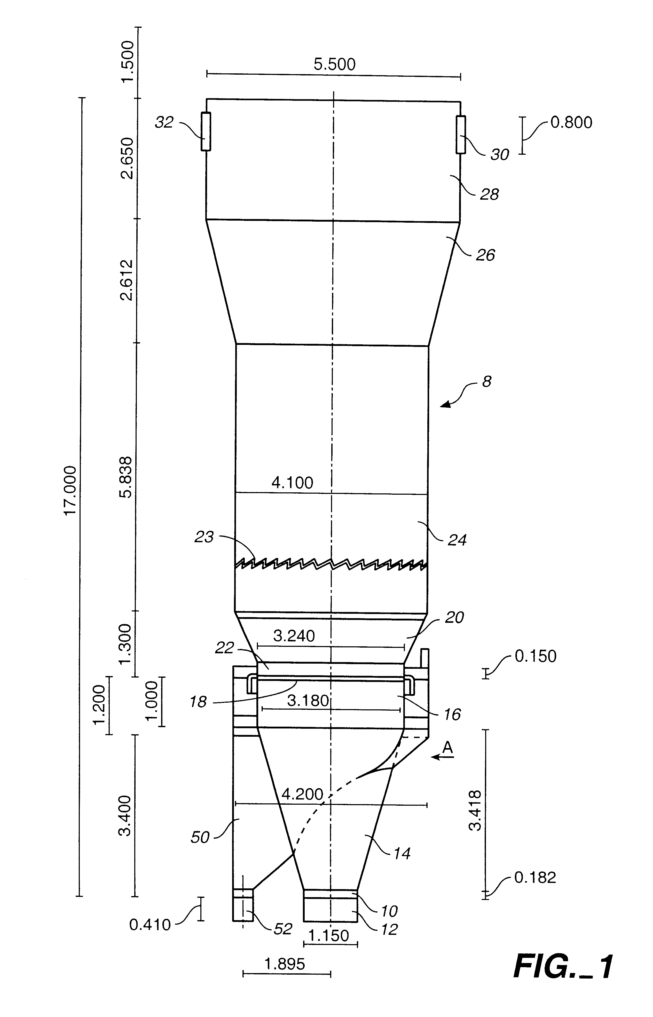
The present invention provides a fluidization coater that can process extremely large particle beds while minimizing particle loss through the exhaust outlet of the coater. The present invention achieves this objective by providing a device having a symmetrical design and features that enable an even and uniform distribution of a fluidization flow homogenously through a bed of particles to efficiently fluidize the bed while not causing particles from the bed to be exhausted through a coater outlet. The design of the present invention includes one or more diverging sections in the coating apparatus that reduce the fluid flow velocity by increasing the diameter along t

Problems solved by technology

The weight of the bed of particles to be coated is limited by the air flow volume and velocity capacities of the fluidization coater.
When too heavy a bed of particles is treated in the coater, the weight of the bed of particles can be too great to be fluidized such that dead spots or dead spaces occur in the bed of particles where no fluidization takes place.
As a result, the batch of particles resulting from such a process are not uniformly coated and can contain large agglomerates of particles, and uncoated particles.
While it has been desirable to process large beds of particles in view of economic concerns, conventional fluidization coaters have been limited in the size of particulate beds that can be processed.
Increasing the air flow and air flow velocity of the fluid flow through a fluidization coater can result in a better ability to fluidize large particle beds, however, in traditional fluidization coaters, increasing the fluid flow and/or fluid flow velocity can lead to a loss of particles through the coater outlet.
Other problems have been encountered in trying to coat a bed of particles with a fluidization coater.
Singular narrow ou

Method used


Image

  • Symmetrical fluidization coater for high capacity manufacturing
  • Symmetrical fluidization coater for high capacity manufacturing
  • Symmetrical fluidization coater for high capacity manufacturing

Examples


Embodiment Construction

The present invention relates to a coating apparatus for forming coated particles such as coated enzyme granules. The coating apparatus includes a symmetrical design that enables uniform, even and thorough fluidization of extremely large volumes and weights of coated particles and particles to be coated. The design eliminates dead spaces within a bed of particles to be treated and provides an even distribution of fluid throughout the particle bed. The design enables the treatment of particle beds weighing in excess of five metric tons, for example, particle beds in excess of ten metric tons. Processing this volume and weight of particles has heretofore been unachievable due to the dead spaces and mud-like cakes that form when large quantities of particles are treated in conventional coating apparatus.

Among the features that promote the achievement of a sufficient fluidization to treat such high volumes of particles, included is a fluid inlet design that provides a laminar flow of fl...


PUM

PropertyMeasurementUnit
Lengthaaaaaaaaaa
Lengthaaaaaaaaaa
Fractionaaaaaaaaaa

Abstract

A fluidized bed coating apparatus is provided and includes a fluid inlet adapted to be connected to a source of fluidizing fluid. The fluid inlet has an entrance opening having a first diameter and an exit opening downstream of the entrance opening. The exit opening has a second diameter that is larger than the first diameter. The inlet also includes an expanding inlet section, between the entrance opening and the exit opening, that has an average diameter that increases in a direction from said entrance opening to said exit opening. A fluid distribution plate is provided adjacent the exit opening and includes a plurality of through-passages to allow the even and distributed passage of a fluidizing fluid therethrough. A chamber having a chamber inlet and a chamber outlet is provided and the fluid distribution plate is positioned between the exit opening and the chamber inlet. The chamber includes at least a first diverging section having an average diameter that increases in the direction from the chamber inlet downstream toward the chamber outlet. The symmetrical design of the coater provides an evenly distributed flow of fluid that enables efficient and complete fluidization and coating of very large particle beds.

Description

The present invention relates to a fluidization coaters for manufacturing coated particles, for example, coated enzyme granules.Fluidization coaters are useful in coating a bed of particulate seed material or core material to form a coated particulate product. In operation, fluidization coaters continuously fluidize a bed of particles to be treated by lifting the bed of particles in a fluid flow of sufficient air flow volume and velocity to lift the particles and form fluidized bed. The weight of the bed of particles to be coated is limited by the air flow volume and velocity capacities of the fluidization coater. When too heavy a bed of particles is treated in the coater, the weight of the bed of particles can be too great to be fluidized such that dead spots or dead spaces occur in the bed of particles where no fluidization takes place. As a result, the batch of particles resulting from such a process are not uniformly coated and can contain large agglomerates of particles, and un...

Claims


Application Information

Patent Timeline
IPC IPC(8): B01J2/00B01J2/16
CPCB01J2/006B01J2/16
Inventor KOSOLA, ANTTIBRAUN, RYSZARDBECKER, NATHANIEL T.CHRISTENSEN, JR., ROBERT L.KYLAKOSKI, VILLEGAERTNER, ALFRED L.
Owner GENENCOR INT INC
Why Eureka
Try Eureka