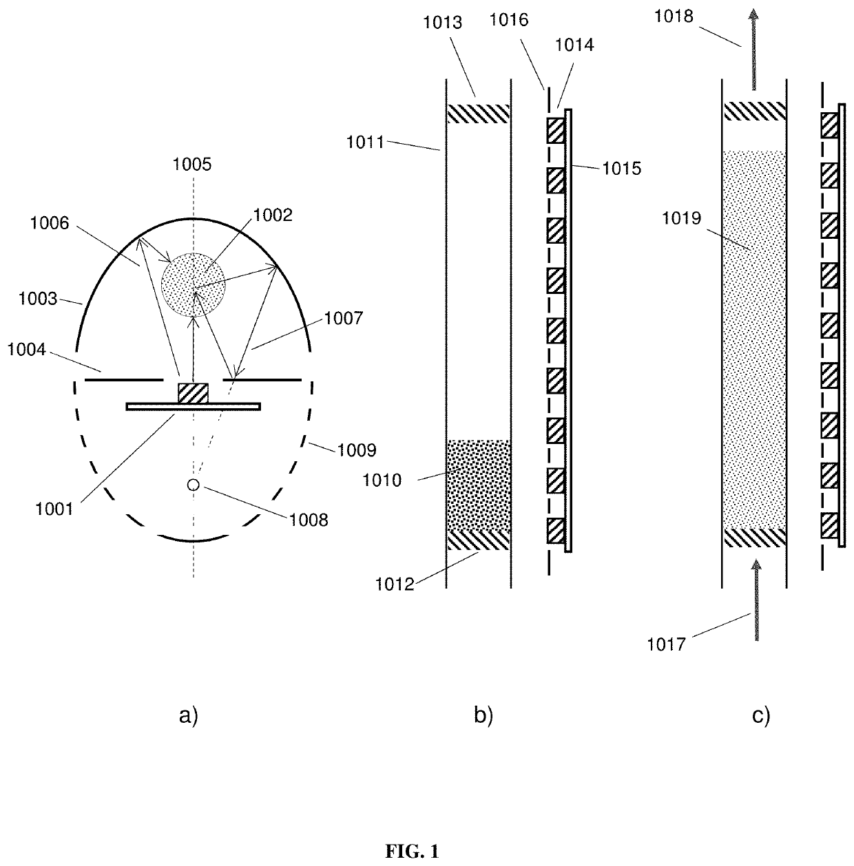
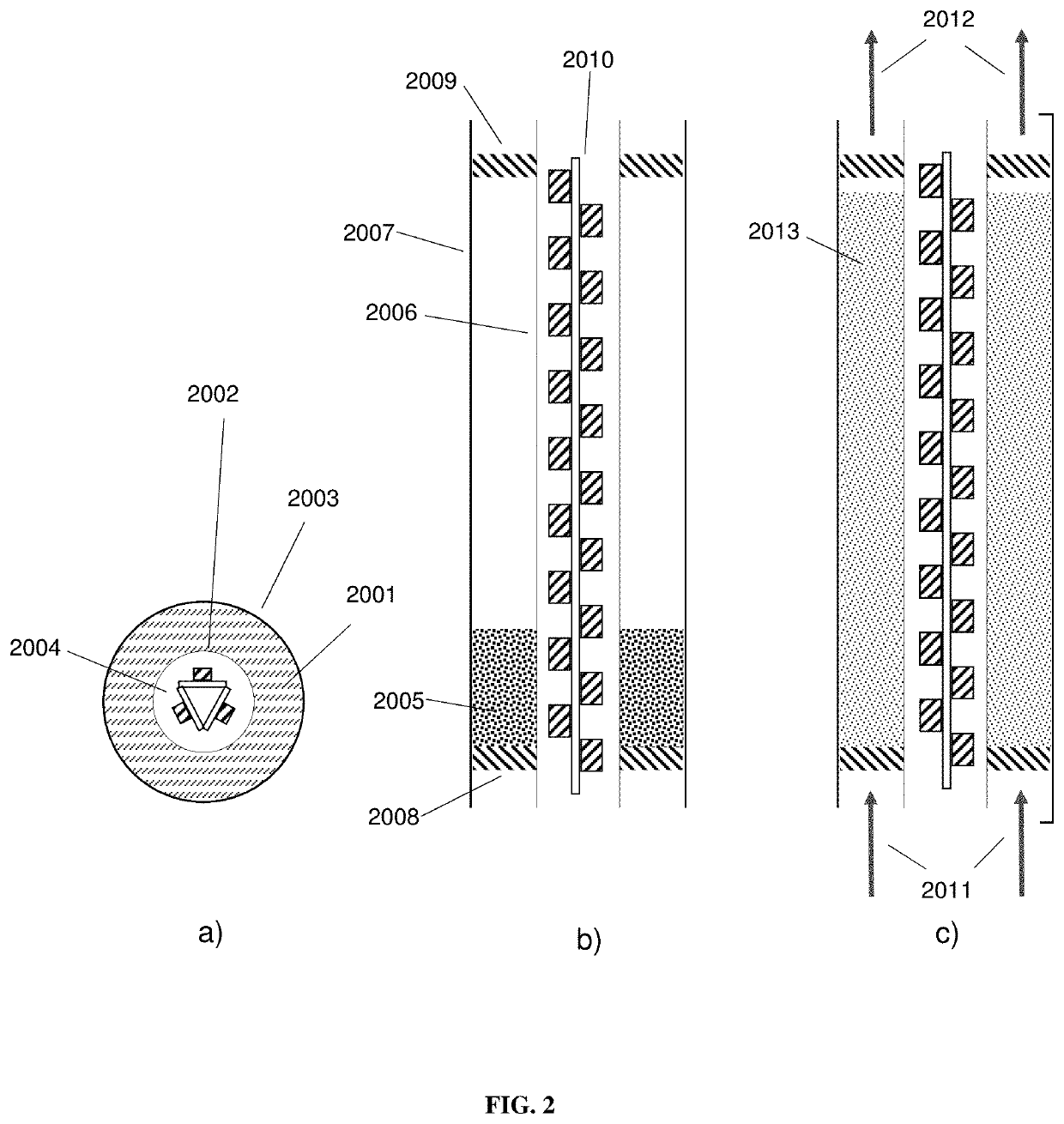
Photocatalytic fluidized bed reactor systems
a photocatalytic and reactor technology, applied in the field of photocatalytic reactor systems, can solve the problems of difficult to regenerate the photocatalyst without shutting down the entire system, high burden of organics on the photocatalyst, and plate damage, so as to reduce the damage of the photocatalyst, improve the conversion rate, and increase the desired conversion rate of chemical species
- Summary
- Abstract
- Description
- Claims
- Application Information
AI Technical Summary
Benefits of technology
Problems solved by technology
Method used
Image

Examples
example 1
[0125]The photocatalytic oxidation of ethylene gas to CO2 and H2O was performed in a closed loop, 100 L test environment comprising a photocatalytic reactor system of Type 3, an ultrasonic humidifier, a humidity controller, and a photoionization detector. The photocatalytic reactor system is similar to that depicted in FIG. 3 and consists of a 2.7 W, 365 nm LED mounted on a heat sink and suspended above the photocatalyst. The LED was operated at full power. The photocatalyst was housed in a conical reactor and held in place by stainless steel meshes above and below the reactor. Fluidization was provided by a variable speed axial fan mounted 2″ from the bottom of the photocatalyst, and all the air was directed through the photocatalytic reactor system using a tube. The relative humidity of the system was maintained at 60%. No additional water was added after the initial relative humidity level was reached. A 10 ppm ethylene cylinder, balanced with air, was used to introduce a charge ...
example 2
[0126]The photocatalytic oxidation of toluene to CO2 and H2O was performed using a continuous 600 sccm, 2 ppm toluene flow that passes once through a photocatalytic reactor of Type 1. The photocatalytic reactor consists of a linear array of 22 365 nm LEDs that are spaced ½″ apart mounted to a heat sink, however, only 3 LEDs are in direct line of site of the photocatalyst. The photocatalyst was housed in a 7 mm inner diameter quartz tube that was aligned vertically and parallel to the LED strip which sits 10 mm away. A reflector was placed on the back side of the reactor. Fluidization was achieved using the 600 sccm polluted gas flow and the photocatalyst was positioned vertically in the tube using a plug of quartz wool. An equilibrium flow of toluene was established for 10 minutes through the reactor before illumination. After illumination, the concentration of toluene was reduced to 0 ppb (limits of detection) of a PID detector calibrated for toluene and remained at that level for ...
example 3
[0127]The photocatalytic oxidation of toluene to CO2 and H2O was performed using the same setup as Example except the quartz tube used had been worn due to attrition by 300 mg of catalyst for 6 weeks at a flow of 1000 sccm. The toluene conversion of the worn tube and a new quartz tube were compared. The transmission of the worn tube was 2× lower than the new tube when measured normal to an LED source with the reactor tube in between. The concentration of toluene was 3 ppm for Example 3. Using the same lights source and reactor geometries, the concentration of toluene decreased to ˜100 ppb for reactor tubes despite the difference in light transmission indicating attrition did not adversely affect performance.
PUM
| Property | Measurement | Unit |
|---|---|---|
| diameter | aaaaa | aaaaa |
| diameter | aaaaa | aaaaa |
| wavelength | aaaaa | aaaaa |
Abstract
Description
Claims
Application Information