Fluidizing a population of catalyst particles having a low catalyst fines content

a technology of catalyst particles and fine particles, which is applied in the field of fluidizing a population of catalyst particles, can solve the problems of increasing the cost of petroleum olefin production, increasing the cost of olefin production, and reducing the efficiency of fluidizing, so as to achieve efficient fluidization

Active Publication Date: 2010-11-09
EXXONMOBIL CHEM PAT INC
View PDF40 Cites 7 Cited by
  • Summary
  • Abstract
  • Description
  • Claims
  • Application Information

AI Technical Summary

Benefits of technology

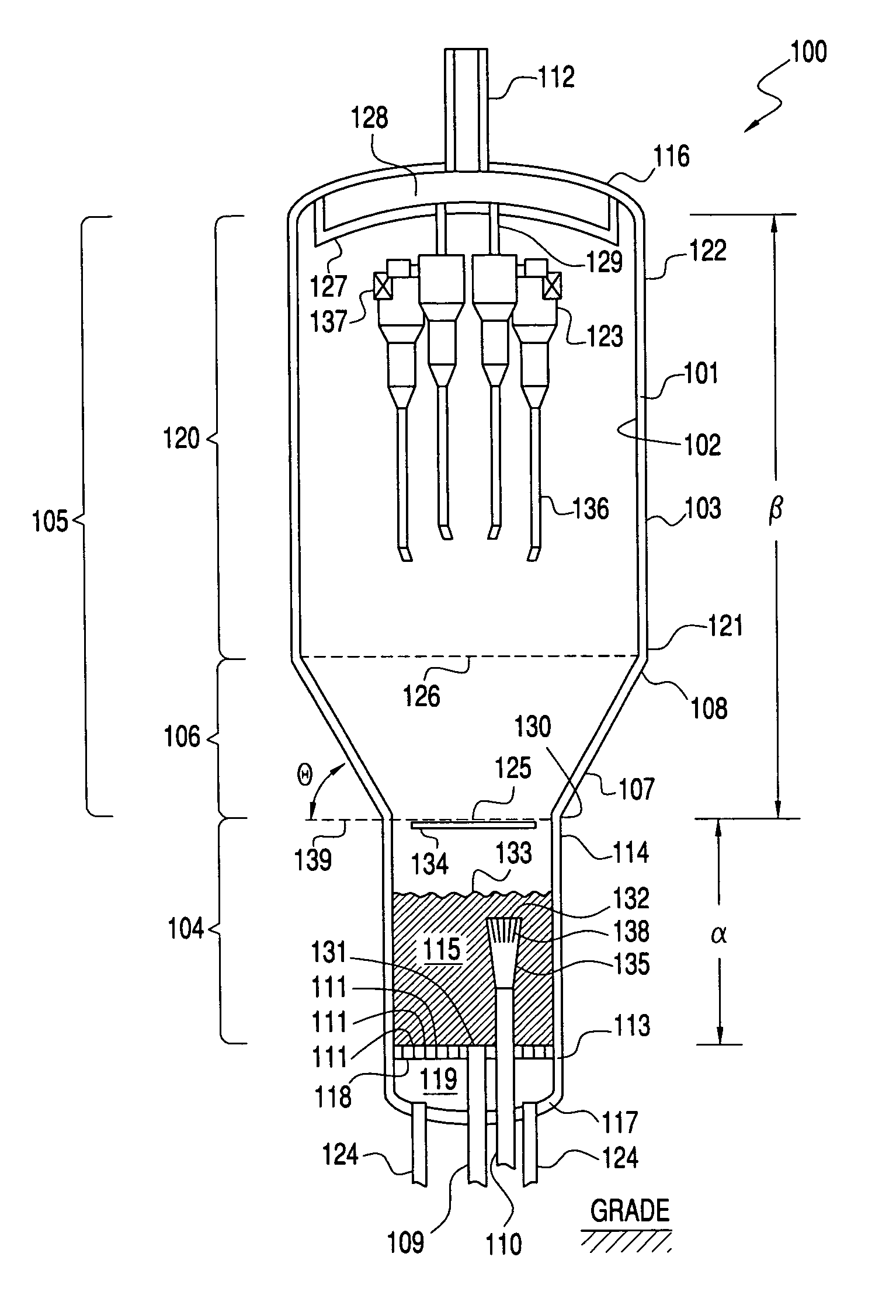
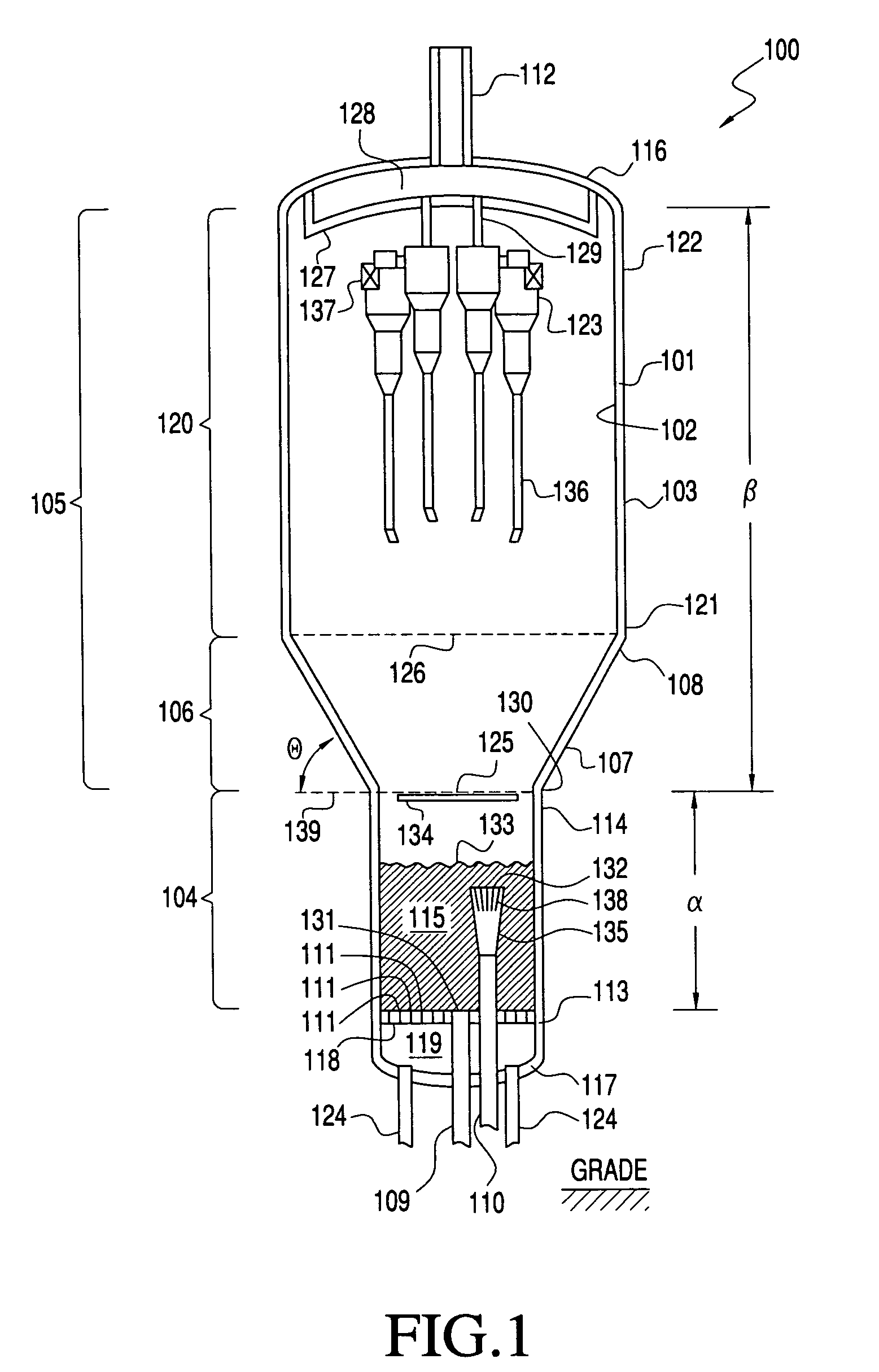
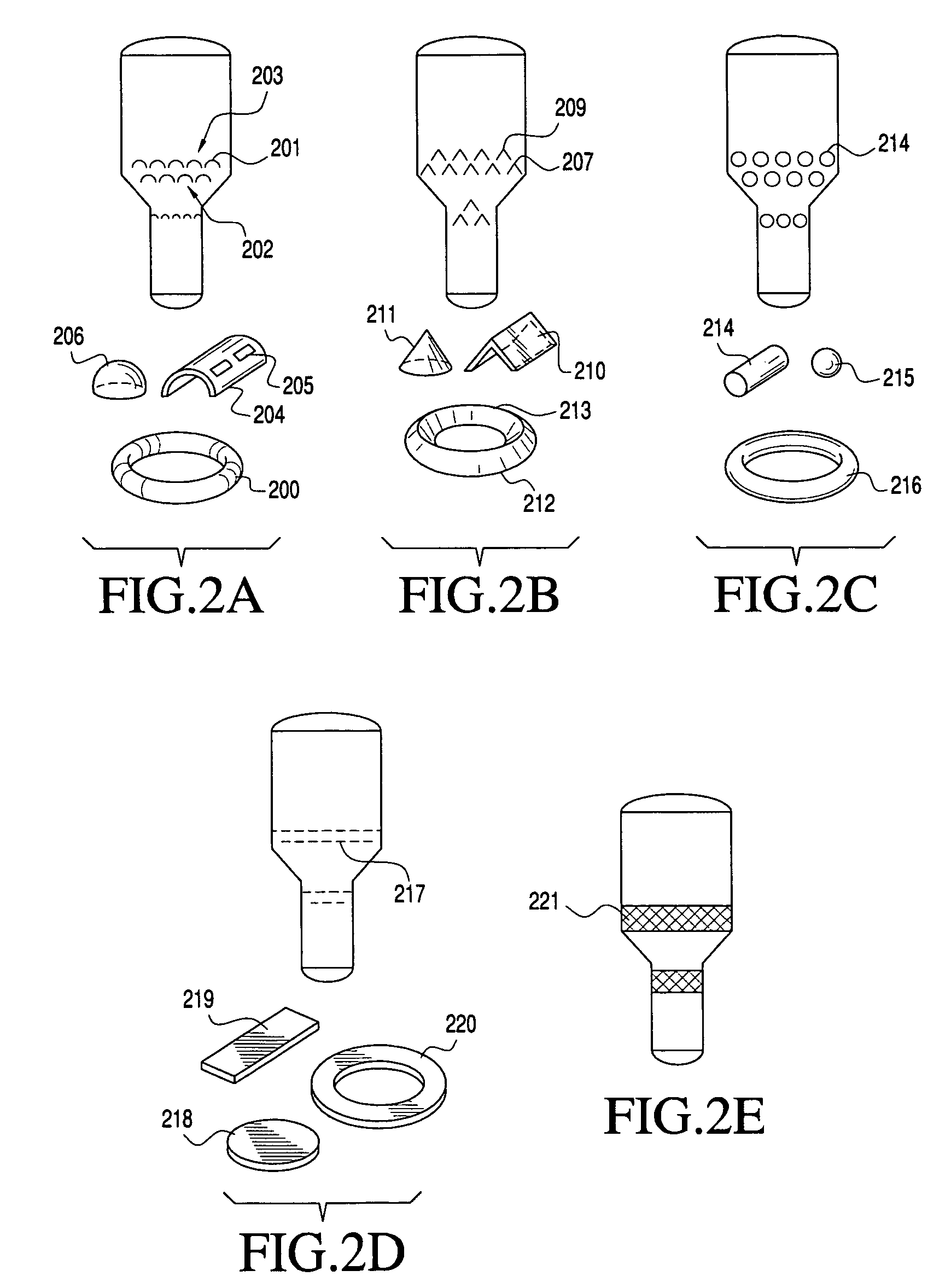
[0013]This invention provides novel processes for efficiently fluidizing a population of catalyst particles having a low catalyst fines content in a fluidized bed reactor. The population of catalyst particles is fluidized in the fluidized bed reactor to form a fluidized bed. In the fluidized bed, the population of catalyst particles contacts one or more obstructing members, e.g., baffles, under fluidization conditions. The present invention is particularly well-suited for fluidizing a population of catalyst particles depleted of catalyst fines in an oxygenate to olefins (OTO) reactor and / or catalyst regenerator.

Problems solved by technology

Because of the limited supply and / or the high cost of petroleum sources, the cost of producing olefins from petroleum sources has increased steadily.
The selective retention of larger particles is particularly a problem for highly attrition resistant particles.
Additional catalyst particles, particularly catalyst fines, may be lost from a catalyst regenerator associated with the OTO reaction system.
Undesirably, a significant amount of entrained catalyst from the regenerator, particularly catalyst fines, is forced out the exhaust outlet with the gaseous byproducts.
One undesirable effect caused by the build up of large catalyst particles in an OTO reaction or regeneration system is that in a large particle rich reaction or regeneration system, the circulating fluid bed or fluidized bed will not operate as well due to the loss of the fine particles, particularly with regard to circulation of catalyst within the standpipes and also with regard to gas distribution within the fluidized bed.
This technique for removing undesirably-sized catalyst particles is inefficient, however, because a significant portion of the desirably-sized catalyst particles are removed from the reaction system with the undesirably-sized catalyst particles.

Method used


Image

  • Fluidizing a population of catalyst particles having a low catalyst fines content
  • Fluidizing a population of catalyst particles having a low catalyst fines content
  • Fluidizing a population of catalyst particles having a low catalyst fines content

Examples


examples 1 and 2

[0196]In Examples 1 and 2, a population of catalyst particles having a low fines content was fluidized in a fluidized bed reactor at a vessel velocity of 0.15 ft / s. The fluidized bed reactor was generally of the form illustrated in FIG. 4, but implemented a sparger and external separation devices. Example 1 included 2 subway grate obstructing members of the type shown in FIG. 4 in the dense phase, and Example 2 included 1 subway grate obstructing member of the type shown in FIG. 4 in the dense phase. The specific particle size distributions for Examples 1 and 2 were as follows:

[0197]

TABLE ILow Fines Content PSDParticle SizeExamples 1 & 2(Microns)(wt %)~0.420–45~1.245–75~42.6 75–120~46.6120–200~8.8

[0198]In these examples, dynamic bed pressure drop measurements were taken over a period of time of 0-1200 seconds. The results of Example 1, shown in FIG. 6, show that the pressure oscillations in the fluidized bed were on the order of + / −1 inch of water when two baffles are implemented. T...

example 3

[0200]In Example 3, a population of catalyst particles having a low fines content was fluidized in a fluidized bed reactor at a vessel velocity of 0.5 ft / s. The fluidized bed reactor was generally of the form illustrated in FIG. 5 having 6 layers of inverted “V” shaped, shed type obstructing members, but implementing a sparger and external separation devices. The specific particle size distribution was as shown in Table I, above.

[0201]In this example, dynamic bed pressure drop measurements were taken over a period of time of 0-1200 seconds. The results of Example 3, shown in FIG. 8, show that the pressure oscillations in the fluidized bed were on the order of + / −0.5 to 1.0 inch of water. This represents particularly good fluidization notwithstanding the low fines content.

example 4

[0202]Example 4 is a comparative example in which a population of catalyst particles having a low fines content was fluidized in a fluidized bed reactor at a vessel velocity of 0.15 ft / s. The fluidized bed reactor did not contain any obstructing members. The specific particle size distribution was as shown in Table I, above.

[0203]In this example, dynamic bed pressure drop measurements were taken over a period of time of 0-1200 seconds. The results of Example 4, shown in FIG. 9, show that the pressure oscillations in the fluidized bed were on the order of + / −4.0 to 5.0 inches of water. This represents very poor fluidization due to the low fines content.


PUM

PropertyMeasurementUnit
particle sizesaaaaaaaaaa
particle diameteraaaaaaaaaa
particle sizesaaaaaaaaaa

Abstract

The present invention relates to processes for fluidizing a population of catalyst particles that are depleted of catalyst fines. In one embodiment, the process includes providing a plurality of catalyst particles in the reactor, wherein the catalyst particles have a d2 value of greater than about 40 microns. The catalyst- particles are contacted with a fluidizing medium under conditions effective to cause the catalyst particles to behave in a fluidized manner and form a fluidized bed. The particles are contacted with one or more primary obstructing members while in the fluidized bed. By fluidizing the catalyst particles in this manner, the catalyst particles can be maintained at an axial gas Peclet number of from about 10 to about 20.

Description

CROSS REFERENCE TO RELATED APPLICATIONS[0001]This application claims the benefit of Provisional Application No. 60 / 640,615, filed Dec. 30, 2004, and Non-Provisional application Ser. No. 11 / 143,390, filed Jun. 2, 2005, the disclosures of which are fully incorporated herein by reference.FIELD OF THE INVENTION[0002]The present invention relates to processes for fluidizing catalyst particles, and more particularly to fluidizing a population of catalyst particles having a low catalyst fines content.BACKGROUND OF THE INVENTION[0003]Light olefins, defined herein as ethylene and propylene, serve as feeds for the production of numerous chemicals. Olefins traditionally are produced by petroleum cracking. Because of the limited supply and / or the high cost of petroleum sources, the cost of producing olefins from petroleum sources has increased steadily.[0004]Various oxygenates, such as alcohols, particularly methanol, dimethyl ether, and ethanol, are alternative feedstocks for the production of...

Claims


Application Information

Patent Timeline
Patent Type & Authority Patents(United States)
IPC IPC(8): C07C1/00
CPCB01J8/0055B01J8/1809B01J8/28B01J8/34C10G11/18C10G3/49C10G3/57C10G3/62B01J2208/00168B01J2208/00495B01J2208/00752B01J2208/00761B01J2208/0084B01J2208/00884C10G2400/20C10G11/182
Inventor BEECH, JR., JAMES H.COUTE, NICOLASSMITH, JEFFREY S.NICOLETTI, MICHAEL PETER
Owner EXXONMOBIL CHEM PAT INC
Why Eureka
Try Eureka