Petroleum recovery and cleaning system and process

a technology for cleaning systems and petroleum hydrocarbons, applied in the field of petroleum hydrocarbon production, recovery and handling, can solve the problems of significant environmental and worker safety hazards, abandonment of operational wellheads, and a number of important problems and limitations in the petroleum industry, so as to achieve effective system and method, enhance petroleum recovery and production, and prevent or minimize subsequent sludge accumulation.

Inactive Publication Date: 2009-09-29
AQUA TECH LLC
View PDF34 Cites 9 Cited by
  • Summary
  • Abstract
  • Description
  • Claims
  • Application Information

AI Technical Summary

Benefits of technology

[0011]In accordance with the invention, an improved system and process are provided for recovering hydrocarbon-based sludge and heavy, relatively viscous oil in a variety of petroleum industry applications, thereby enhancing petroleum recovery and production. In addition, the system and process of the present invention may be used for separating accumulated oil-based sludge coatings from process equipment surfaces in a manner that effectively prevents or minimizes subsequent sludge accumulation thereon. Further, the invention provides an effective system and method for separating and cleaning suspended solid contaminants such as sand and silt particles to provide an oil product of improved quality, and a separated solids by-product which can be used or disposed in a environmentally compatible manner.
[0013]The dispersion fluid comprises a non-toxic, non-solvent based, and environmentally friendly solution, which effectively fluidizes the petroleum sludge or heavy oil deposit. In general, the specific final pH of the dispersion fluid is directly proportional to the viscosity of the sludge or heavy oil deposit, i.e., a higher pH level facilitates fluidization of more viscous petroleum products. The dispersion fluid is injected under relatively high pressure and high shear conditions into contact with the sludge material, resulting in separation of the petroleum-based constituents from inorganic surfaces such as process equipment surfaces and inorganic solids such as sand and silt particles. Separation of these constituents may be enhanced by additional mechanical means such as by applying sonic or ultrasonic vibration, or hydroblasting, and the like.
[0014]The surface area of the inorganic constituent (process equipment surface, or solid contaminant such as sand or clay particles) is thus effectively stripped free of hydrocarbon molecules adhered thereto, and the negatively charged dispersion fluid is believed to reverse the positive or neutral ionic charge of the inorganic surface area so that subsequent re-adherence or re-attachment of hydrocarbon molecules thereto is effectively resisted. Some of the petroleum constituent is also believed to adsorb the dispersion fluid and thereby assume a negative ionic charge for improved separation from the inorganic constituent. This technique effectively reduces the viscosity of the petroleum constituent to an easily recoverable fluidized state, which is independent of temperature.
[0015]In one form, the mixture or slurry of fluidized petroleum, solids contaminants, and dispersion fluid is settled within a settling tank, wherein the petroleum product floats to the top while particulate settles to the bottom as sediment. The dispersion fluid remains generally within a central or mid-level region of the settling tank where it can be removed for re-use. The fluidized petroleum product can be removed as by skimming for processing by conventional refinery methods, and thus represents a recovered, otherwise waste or unusable petroleum resource. This particulate sediment such as sand and clay particles can be separated from the fluidized petroleum product can be recycled for alternative uses such as incorporation into paving compositions, or disposed down-hole or in a landfill or the like, all in an environmentally friendly manner.
[0016]The system and method can be utilized for in situ fluidization of in-ground petroleum deposits including sludge accumulated in the region adjacent a well-head, or accumulated upon process equipment surfaces such as pumps and valves and the like, thereby improving oil field production. The invention may also be used for fluidizing and recovering petroleum sludge collected within settling tanks or waste ponds, and / or for separating the petroleum sludge component from the inorganic solid component for independent reclamation.

Problems solved by technology

The petroleum industry, however, is plagued by a number of important problems and limitations, some of which pose significant environmental and worker safety hazards.
More particularly, as crude oil is extracted from a subterranean deposit over a period of time, the subterranean strata particularly in the region close to the extraction pump or well-head gradually becomes clogged or plugged with a highly viscous hydrocarbon-based sludge that is typically mixed with inorganic material such as sand and clay particles and the like.
In some instances, production from an operational but sludge-clogged well-head can become uneconomical with as much as 85% of the oil deposit remaining in the ground, resulting in abandonment of the operational well-head, and, in some cases, costly drilling and installation of a replacement well-head at a different location to resume oil field production.
Once again, over time, these sludge coatings build up and clog these process equipment surfaces, resulting in reduced pumping and related flow rates.
Periodic cleaning of accumulated sludge coatings from process equipment surfaces has been difficult, and normally involves the use of and exposure of workmen to toxic materials and dangerous working conditions, sometimes with minimal cleaning effectiveness.
In addition, the accumulated sludge deposits cleaned from such process equipment surfaces, together with solvent-based cleaning solutions, comprise toxic wastes, which are subject to costly handling and disposal.
This tank sludge is very difficult to fluidize and remove from the bottom of a settling tank or pond, and, once again, requires exposure of workmen to toxic materials and dangerous working conditions, and further represents a highly toxic waste product.
As noted above, such organic compounds can be carried with the crude oil and precipitate out at various stages of the petroleum production process, resulting in sludge accumulation within tanks and / or blockages within pumps, valves, pipelines, and other handling and processing equipment.
When destabilized during production or processing, asphaltene can deposit onto contacted surfaces as a “glue and mortar” type precipitate, resulting in hardening other components of the crude oil to form extremely viscous and virtually solid sludge deposits.
Such complex mixtures often form deposits that cannot be re-fluidized by simple reheating of the system or by the introduction of aromatic solvents.
Instead, current systems and methods have relied upon a variety of chemical and mechanical methods which expose workers to very toxic and dangerous conditions and chemicals, and often significantly increase the amount of a waste stream that contains hazardous materials and is thus subject to complex and costly disposal methods.
In addition, current solvent-based chemical compositions used to remove and / or clean heavy oil, oils from tar sands, and residual down-hole sludge in a well are often very expensive yet offer minimal if any success.

Method used


Image

  • Petroleum recovery and cleaning system and process
  • Petroleum recovery and cleaning system and process
  • Petroleum recovery and cleaning system and process

Examples


example 1

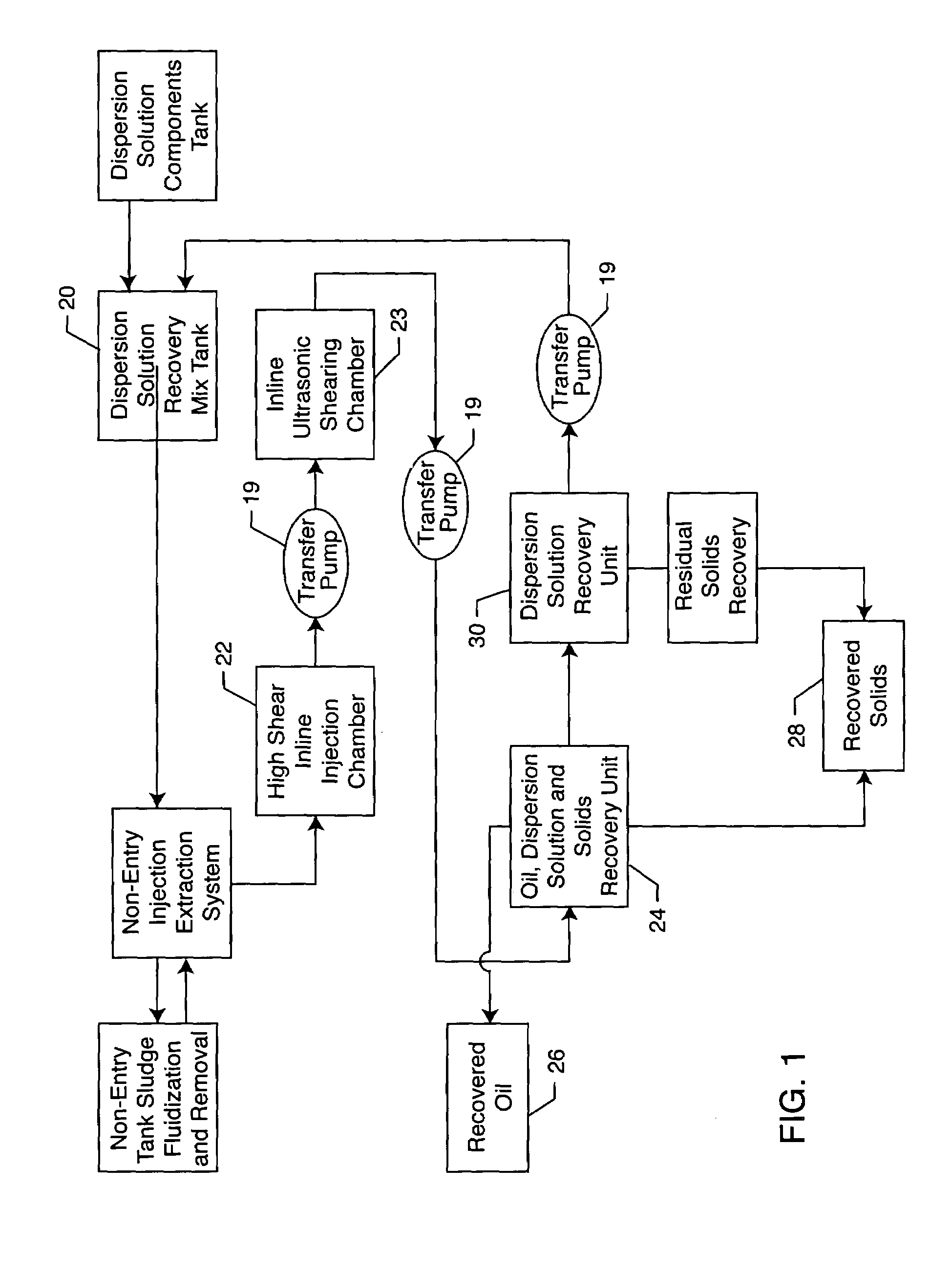
[0046]The system and process of the present invention are useful in fluidizing petroleum-based sludge accumulated at the bottom of a settling or storage tank of the type commonly used in a refinery facility, to permit solid contaminants and the like to fall out of suspension and accumulate at the tank bottom as a sediment in the form of a heavy, petroleum-based and almost solid waste product. Following an appropriate settling interval, the resultant clarified and more viscous oil product within an upper region of the settling tank is skimmed off for appropriate refining processes.

[0047]The objective of the present invention is to economically remove and dispose of this petroleum-based sludge, which may comprise on the order of about 3,500 barrels (bbls.) of accumulated material at the bottom of a typical refinery storage / settling tank having an overall petroleum storage capacity on the order of about 100,000 bbls., in a manner consistent with minimal disruption of refinery operation...

example 2

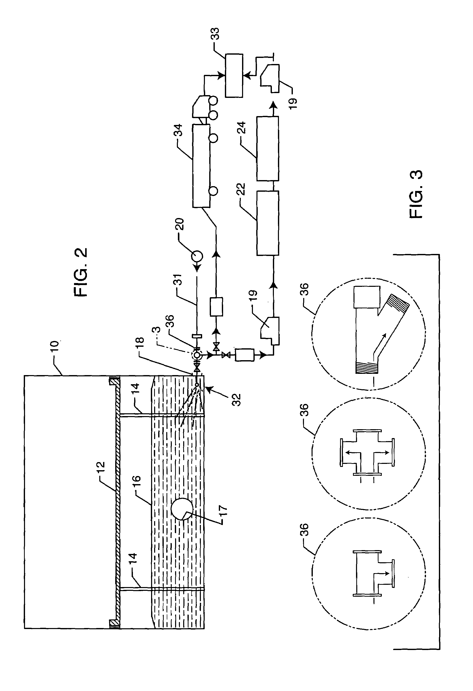
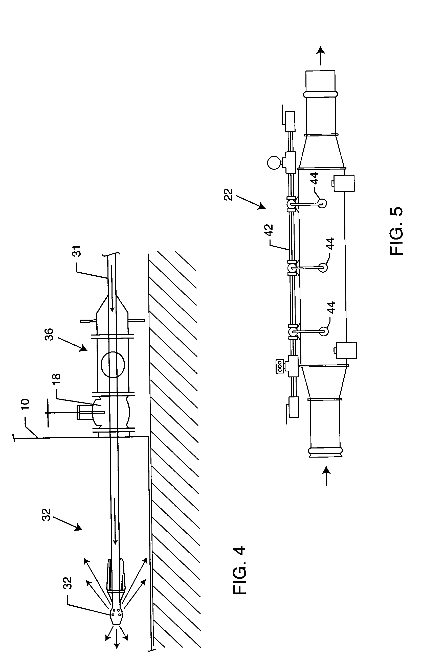
[0051]In an alternative exemplary test of the invention, accumulated petroleum-based sludge is again removed from the bottom of a refinery storage settling tank, similar to the test described in Example 1 above, but without direct worker access to the tank interior. Accordingly, in this Example 2, workers were not subjected to the potentially toxic atmosphere within the tank interior. The storage / settling tank had a diametric size of about 90 feet, and included about 5,700 bbls. of accumulated petroleum-based sludge in sludge dunes ranging from about 4 to 6 feet in height. In this particular test, the accumulated crude oil sludge included a significant volume of suspended sand particulate and some proprietary catalyst, resulting in heavy oil deposits that would be very difficult to remove.

[0052]In this test, the dispersion fluid (prepared as described in Example 1, with a sodium metasilicate concentration of about 0.1%) was injected into the tank interior at a flow rate of about 6 g...

example 3

[0055]In some instances, there is minimal commercial interest or opportunity in processing fluidized petroleum-based sludge material recovered as described, i.e., in Examples 1 and 2 above. In that event, economic and preferably environmentally compatible disposal represents another preferred option. Accordingly, as one application of the present invention, fluidized sludge material can be disposed by pumping such material down-hole into an exhausted or otherwise abandoned oil well, as opposed to traditional yet costly landfill disposal.

[0056]In this example of the invention, petroleum-based sludge material including very viscous asphaltene rich sludge, sand and clay was fluidized in the manner and using the dispersion fluid as described above in Example 1. Such sludge material was successfully removed from refinery storage tanks into vacuum trucks, transported to an abandoned well site, and then pumped or injected down-hole for disposal. Volatile hydrocarbon material was substantia...


PUM

PropertyMeasurementUnit
pressureaaaaaaaaaa
pressureaaaaaaaaaa
pressureaaaaaaaaaa

Abstract

A system and process are provided for recovering and / or cleaning residual or waste petroleum products such as sludge accumulated within a storage tank or upon process equipment surfaces, or from inorganic materials such as sand or clay, and the like. The system and process include a negatively charged aqueous-based dispersion fluid, which is contacted with the petroleum product under controlled relatively high pressure and high shear conditions for fluidizing hydrocarbon molecules and for preventing such molecules from adherence to process equipment surfaces, or contaminants such as sand or clay. Additional mechanical separation as by subjecting the mixed petroleum product and dispersion fluid slurry to sonic vibration may also be employed. The thus-fluidized slurry of petroleum products, dispersion fluid, and inorganic materials can be separated by conventional techniques, as by settling and / or flotation, for further individual processing and / or re-use.

Description

[0001]This application claims the benefit of U.S. Provisional Application No. 60 / 538,819, filed Jan. 23, 2004.BACKGROUND OF THE INVENTION[0002]This invention relates generally to the field of petroleum hydrocarbon production, recovery and handling. More specifically, this invention relates to an improved system and method for fluidizing, separating, and recovering highly viscous residual petroleum products such as sludge and the like which can adhere to inorganic surfaces such as process equipment including pumps, valves, and flow conduits and the like, as well as contaminant solids such as sand or clay and the like. The invention mechanically and chemically separates the residual petroleum products from the associated inorganic material to facilitate processing, to recover otherwise waste or unusable petroleum products, and to clean contaminant solids such as sand or clay in a manner accommodating environmentally compatible re-use or disposal.[0003]In the petroleum industry, subter...

Claims


Application Information

Patent Timeline
Patent Type & Authority Patents(United States)
IPC IPC(8): C10G1/04B01D17/00B01D17/04B01D21/00B01J8/20B01J19/00B08B3/02B08B3/08B08B9/00B08B9/02B08B9/08B08B9/093B09C1/02C09K3/32C09K23/00C10G1/00C11D3/08C11D11/00
CPCB01D17/00B01D17/047C11D11/0052C10G1/00C09K3/32B09C1/02B08B9/0933B08B9/027B08B9/00B08B3/02B01J19/0086B01J8/20B01D21/0006B01D21/0018B01D21/01B01D21/10B01D21/2405B01D21/2433B01D21/2461B01F17/0021B01F17/0028B01F17/0057B01D17/0205B01D17/0208B01D17/0217B01D17/04B01D2221/04B01D17/12C09K23/00
Inventor COLIC, MIROSLAV
Owner AQUA TECH LLC
Why Eureka
Try Eureka