Road vehicle axle sensor

a technology for vehicle axles and sensors, applied in the direction of resistors, conductors, traffic control systems, etc., to achieve the effect of accurate and repeatable vehicle passage indications

Inactive Publication Date: 2002-10-22
INTERNATIONAL ROAD DYNAMICS
View PDF23 Cites 12 Cited by
  • Summary
  • Abstract
  • Description
  • Claims
  • Application Information

AI Technical Summary

Benefits of technology

The invention is thus concerned with a sensing device which utilises a phosphor bronze membrane switch in an outdoor, highly-destructive environment of a road for producing accurate, and repeatable, indications of vehicle passage, velocity and the like useful information.

Problems solved by technology

Consequently, pressure applied upon the device results in current flow through the printed circuit across the gap area beneath the pressure.

Method used


Image

  • Road vehicle axle sensor
  • Road vehicle axle sensor
  • Road vehicle axle sensor

Examples


Embodiment Construction

(a) Description of FIG. 1

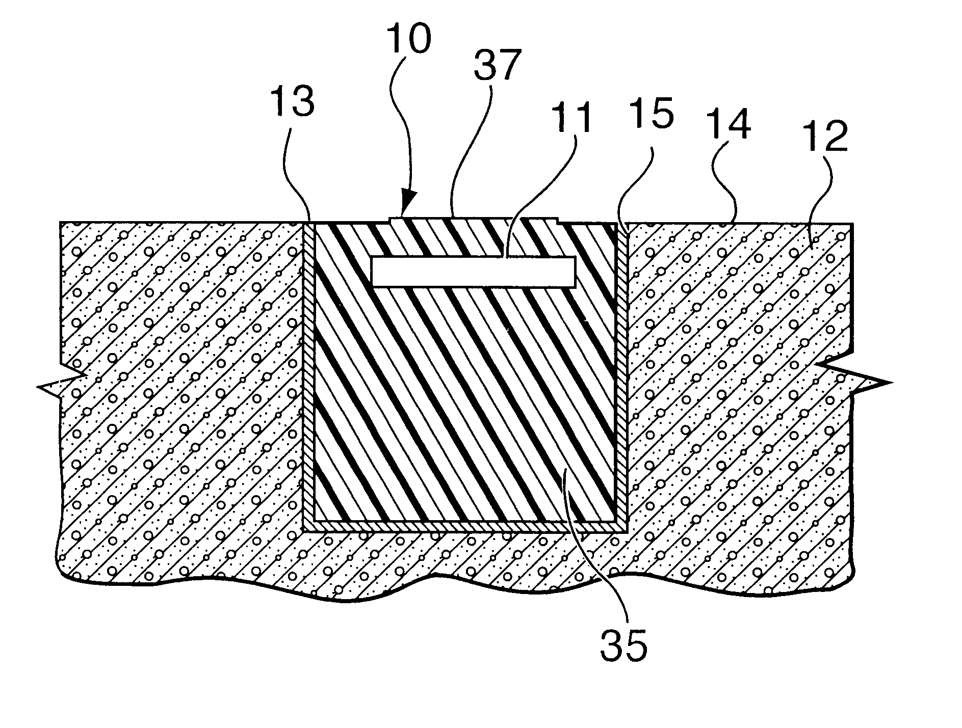
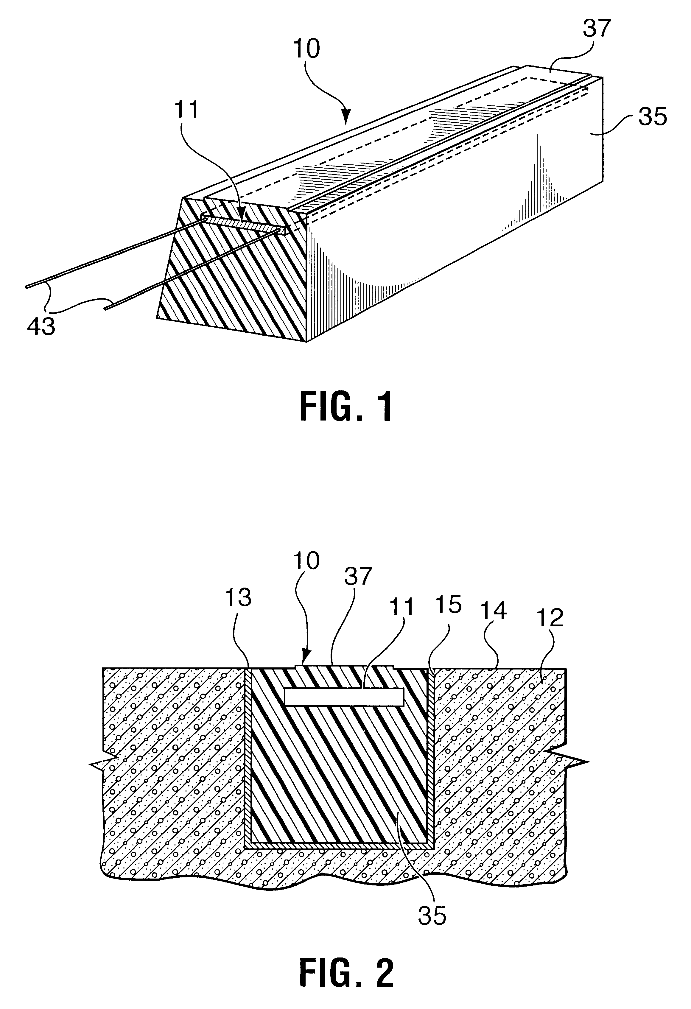
As seen in FIG. 1 the sensor 10 of one embodiment of the present invention includes a membrane switch, generally designated 11, which is embedded in a block 35 of a resilient, rubber-like material, e.g., a polyurethane rubber. Lead wires 43 extend out from the membrane switch 11. The membrane switch 11 is embedded a short distance below the top surface 37 of the block 35.

(b) Description of FIG. 2

FIG. 2 illustrates sensor 10 which is arranged within a slot of saw-cut like groove 15 which is formed in the upper surface 14 of a road 12. The upper surface 14 may be on a highway 12 or the like where the number of vehicles passing over the road are to be determined. Alternatively, the upper surface 14 may be part of the roadway 12 around a truck weighing station or it may even be within a factory floor, wherein the movement of vehicles or the loads upon vehicles are a matter of concern. Typically, the groove 15 may be formed in the road 12 using a conventional roa...


PUM

PropertyMeasurementUnit
resilientaaaaaaaaaa
electrically-conductiveaaaaaaaaaa
electrically non-conductiveaaaaaaaaaa

Abstract

An improved vehicle road sensor is provided for signalling the passage of a vehicle over a predetermined location on a roadway. The vehicle road sensor includes a membrane switch which includes a first member and a second member. The first member includes a non-conductive substrate, a pair of electrically-conductive stripes upon the non-conductive substrate, an electrically non-conductive gap separating the electrically-conductive stripes, and an electrically-conductive lead connected to each electrically-conductive stripe. The second member includes an electrically-conductive strip which is superposed upon the electrically-conductive stripes on the first member. The second member is normally out of electrical contact with the electrically-conductive stripes on the first member. The second member is sufficiently flexible, so that, under a compressive load, it deflects to shunt across the electrically non-conductive gap, thereby to permit electric current to flow from the electrically-conductive stripes to the second member. Various arrangements of separate, but connected sensitive zones may be provided along the length of the sensor. Vehicle wheels of different widths would activate a different number of active sections, thereby approximating tire widths, for detecting the presence of one tire or two tires.

Description

(a) Field of the InventionThis invention relates to a sensing device which preferably is flush with the surface of a road, for sensing the passage of vehicles over the device and, if connected with a properly programmed computer, determines the presence of the vehicle passing over the device.(b) Description of the Prior ArtGovernment agencies often require the submission of reports concerning truck travel at specific locations on roadways before authorizing funding for the repair and improvement of such roadways. A number of classifying machines are currently used to provide such reports concerning truck travel. Typically, they require two axle detector inputs which are positioned a known distance apart. The classifying machine measures the time interval between axles, calculates the speeds at which the axles are travelling, counts the number of axles travelling at the same rate of speed, and then, depending upon results, records the vehicle type in a predetermined classification bi...

Claims


Application Information

Patent Timeline
Patent Type & Authority Patents(United States)
IPC IPC(8): E01F11/00G08G1/02H01H3/02H01H3/14
CPCE01F11/00G08G1/02H01H3/142
Inventor TAYLOR, BRIAN
Owner INTERNATIONAL ROAD DYNAMICS
Why Eureka
Try Eureka