
Printing method and a printing apparatus

a printing apparatus and printing method technology, applied in the direction of printing mechanisms, visual presentation using printers, instruments, etc., can solve the problems of reducing the image quality in the form of density variations of printed images, elongating the print time, and affecting the image quality of the printed image, so as to prevent beading

Inactive Publication Date: 2002-11-05
CANON KK
View PDF19 Cites 16 Cited by
  • Summary
  • Abstract
  • Description
  • Claims
  • Application Information

AI Technical Summary

Benefits of technology

of the above-mentioned Patent to prevent beading between each pixel, it is characterized that each pixel printed in a single scanning is alternate in the horizontal and vertical directions (not adjoining each other).
Moreover, the Japanese Patent Publication No. 63-38309 (1988) also discloses that, although this Publication is not restricted to a color printer, a construction for performing back-and-forward printing using a diced form (checker pattern) is disclosed. An object of the invention in the Publication is to prevent adjoining dots from being successively printed and to prevent dot-distortion from occurring by avoiding printing an adjacent dot before the printed dot is dried. Therefore, according to this invention, similarly to the above-mentioned U.S. Pat. No. 4,748,453, the thinning-out mask is restricted to a diced form (checker pattern).
As a solution of the harmful effect of the above-described color irregularity, the invention disclosed in Japanese Patent Application Laid-open No. 6-22106 (1994) is mentioned. According to this invention, a group of m.times.n pieces of pixels is used as a unit for printing, and printing is performed by using an arranging matrix in which the groups are not adjacent to each other. The Application discloses such an effect as an amount swelling out to a blank paper area has been reduced by printing a batch of m.times.n pieces of pixels, and a difference between prioritized colors in forward and backward printings has been eliminated to reduce the harmful effect of color irregularity.
The present invention is made considering the above-mentioned problem, and the purpose is to make it possible to form a high quality image at a high speed, namely, to make it possible to print a photographic image without color irregularity at a high speed.

Problems solved by technology

As to the uniformity in particular, slight variations among individual nozzles that are produced during the manufacture of a multi-nozzle head formed integrally with many nozzles (in this specification the nozzle generally refers to an ejection opening, a liquid passage communicating with the ejection opening and an element for generating energy used to eject ink) influence the amounts of ink ejected from the individual nozzles and the directions of ink ejection during printing and eventually degrade the image quality in the form of density variations of the printed image.
This however elongates the print time, which means that there is a trade-off relation between the image quality and the print time.
However, although this method has been able to cope with the predetermined dither pattern for the purpose, it has been difficult to equally cope with all the binarization methods.
The above-mentioned divided printing has had a problem that time and cost required for printing a sheet of paper increases as the number of division increases, and the throughput of printing decreases.
However, in a color ink-jet printing apparatus, it has been difficult to realize bi-directional printing due to the below described factors.
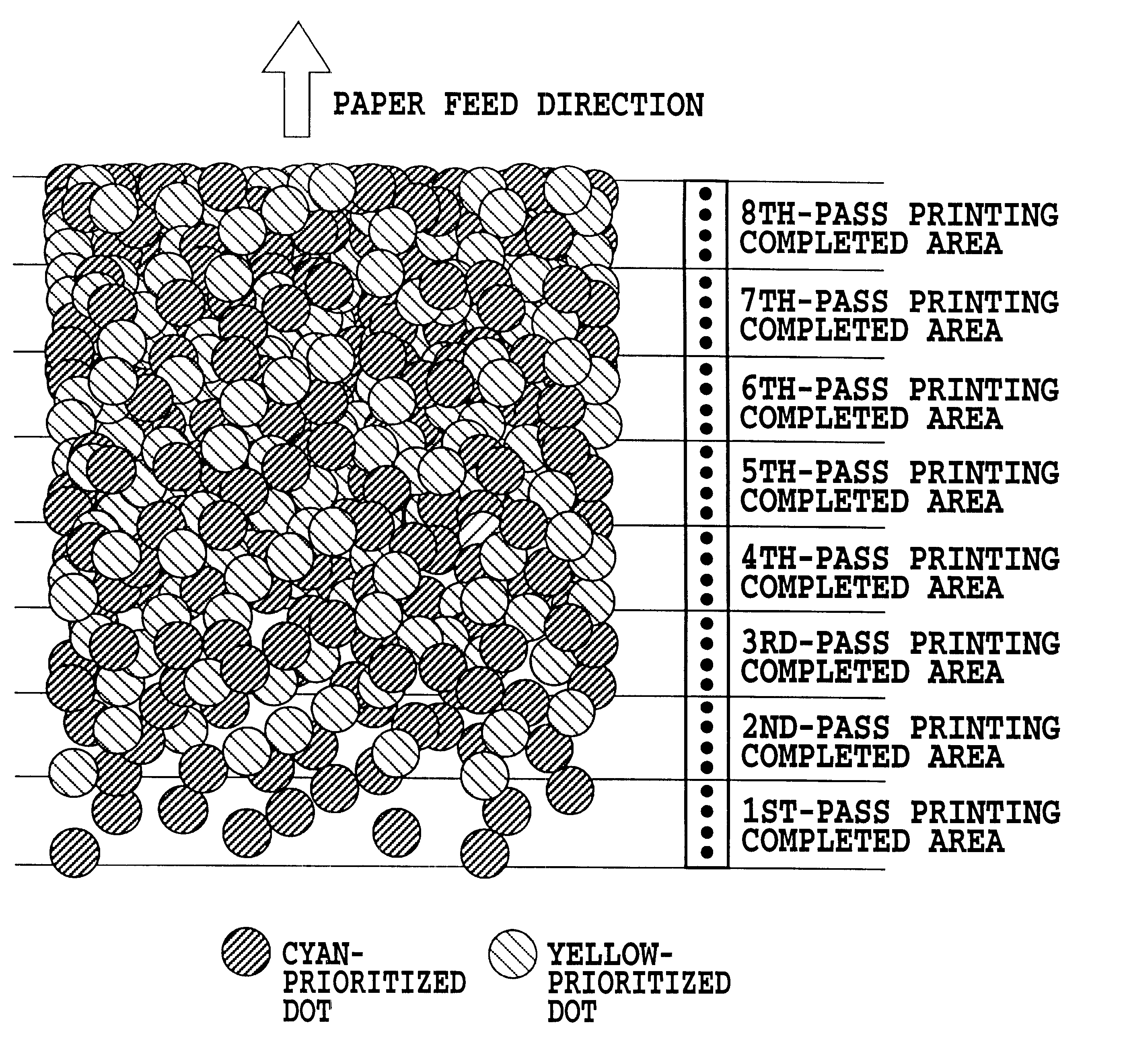
Namely, if print-scanning is carries out without considering the divided printing and the paper is fed by an amount of the y-directional head width between the forward and backward scans, the green area with a cyan tone and the green area with a yellow tone are alternately repeated at each head width in the y direction, and this causes deterioration in quality of the green image which should be even.
However, even though the divided printing is performed according to the checker pattern disclosed in the Publication, the harmful influence of color irregularity is not completely solved yet.
Although the description has been made here assuming that a checker patterned mask was applied, a random mask printing method disclosed in the before-mentioned Japanese Patent Application Laid-open No. 7-52390 (1995) has brought a similar result, and since two areas with different prioritized colors existed alternately, color irregularity has still appeared also in divided printing and deteriorated an image, and a bi-directional printing has been made difficult.
However, the technique disclosed by the above-described Japanese Patent Application Laid-open No. 6-22106 (1994) has not suited for printing a high quality photographic tone image which is required nowadays.
Namely, although the invention has been able to fully cope with a desktop publishing, and a printing for images consist of graphics or text, it could be harmful to a photographic image quality which is in great demand in recent years.
Therefore, under the existing circumstances, it is general to cope with the problem by applying a random mask printing method with increasing the number of divided printing, however, when bi-directional printing is carried out to increase a throughput, color irregularity still remains to some extent and the problem is still not fully coped with.
However, color irregularity occurs on some kinds of printing media, and is strictly evaluated especially in a mode requiring a highest quality image.

Method used


Image

  • Printing method and a printing apparatus
  • Printing method and a printing apparatus
  • Printing method and a printing apparatus

Examples


second embodiment

Next, the present invention will be described. This embodiment adopts 4-pass printing, and a covering ratio is calculated by also adopting the effect of the collective dot mask described in the above-mentioned Japanese Patent Application Laid-open No. 6-22106 (1994).

first embodiment

FIG. 14 shows a collective dot used in this embodiment, and printing is performed in pixel arrangement in a constitution unit of 4 dots in the main scanning direction.times.1 dot in the sub scanning direction. If it is assumed that plural dots adjoin each other like this, the overlapping areas of each dot are offset in the calculation of the covering ratio and thus, the covering ratio value becomes smaller. If a printing apparatus similar to the one used in the first embodiment is used also in this embodiment, the covering ratio of one collective dot is 64%. However, it is assumed here that each collective dot unit of m.times.n=4.times.1 does not adjoin each other. The first pass can be increased in the data printing ratio by the decrease in the covering ratio.

Since 4-pass printing is adopted in this embodiment adopts, the printing ratio is 25% in each print-scanning if data are equally divided. If printing is carried out by using the collective dot unit of 4.times.1 dots, the cover...


PUM


Abstract

To make it possible to print a smooth image without color irregularity at a high speed by a printing apparatus using a color ink-jet head provided with plural arrays of ink ejection openings side by side in the direction of the main scanning corresponding to different color inks, moving this head to scan reciprocally, and also adopting a multi-pass printing method for divided printing on a certain area by scanning at plural times with the color ink-jet head. In the multi-pass printing using the color ink-jet head, an ink firstly landed on a certain area determines a prioritized color influential on the color tone. Moreover, a printing medium is largely covered by a first two-pass printings. Namely, if it is possible to suppress the color irregularity in the first two passes, a harmful influence on a whole image by the color irregularity can remarkably reduced, therefore, the first pass data printing ratio to the area is set smaller than that of the second pass and thereafter.

Description

This application is based on Japanese Patent Application No. 11-237298 filed on Aug. 24, 1999, the content of which is incorporated hereinto by reference.1. Field of the InventionThe present invention relates to a printing method and a printing apparatus, and is particularly suited for adjusting the positions of ink dots in a printing apparatus of an ink jet system. In addition to general printing apparatus, the present invention can also be applied to copying machines, facsimiles with a communication system, word processors with a printer, and industrial printing apparatus combined with a variety of processing devices.2. Description of the Related ArtAn image printing apparatus of so-called serial scan type, which executes the print operation while scanning a print head, or a printing unit, over a print medium, has found a variety of image forming applications. The ink jet printing apparatus in particular has in recent years achieved high resolution and color printing, making a sig...

Claims


Application Information

Patent Timeline
Patent Type & Authority Patents(United States)
IPC IPC(8): B41J19/14B41J19/00B41J2/21G06K15/10G06K15/02H04N1/40B41J2/01B41J2/205B41J2/51
CPCB41J2/2132B41J19/147G06K15/107H04N1/40043G06K2215/0094
Inventor FUJITA, MIYUKIKONNO, YUJIMAEDA, TETSUHIRO
Owner CANON KK
Learn More