Electrical connector contact pin

a technology of contact pins and connectors, applied in the direction of coupling contact members, coupling device connections, electrical devices, etc., to achieve the effect of high manufacturing tolerances

Inactive Publication Date: 2002-11-05
RADIALL SA
View PDF6 Cites 44 Cited by
  • Summary
  • Abstract
  • Description
  • Claims
  • Application Information

AI Technical Summary

Benefits of technology

In other words, the connector element does not suffer plastic deformation which would reduce the forces which it exerts on the sheath and the peg by resilience.
A further essential advantage of the contact pin of the invention is that it can tolerate relatively high manufacturing tolerances, since the elasticity of the connector element can to a large extent compensate for any defects in dimensioning between the parts.

Problems solved by technology

With such contact pins, a problem arises when interconnecting the front and rear parts, since said coupling must be carried out simply and rapidly and must result in good electrical contact by introducing a minimum amount of disturbance to the electrical signal transmitted by the pin.

Method used


Image

  • Electrical connector contact pin
  • Electrical connector contact pin
  • Electrical connector contact pin

Examples


Embodiment Construction

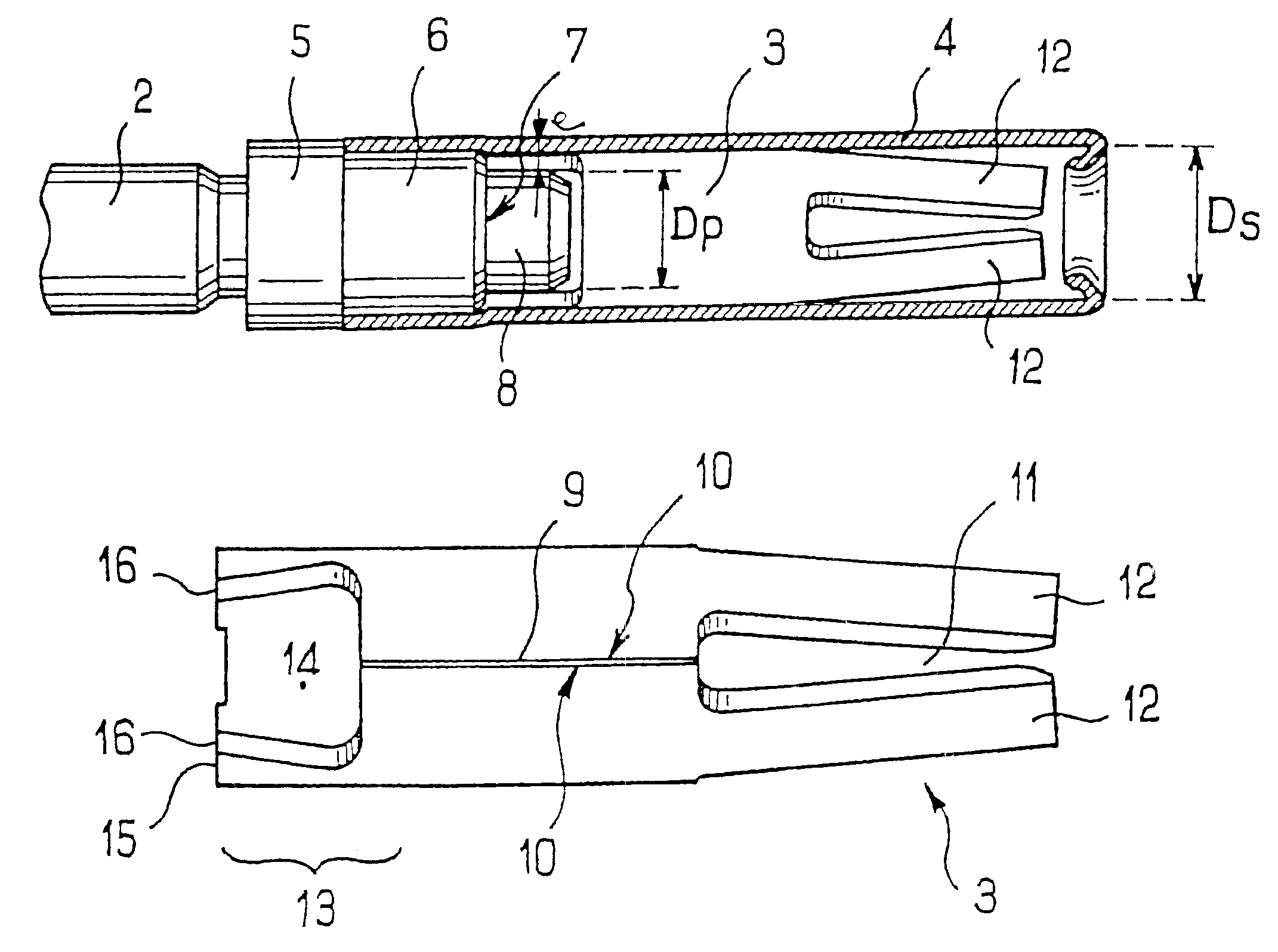
Contact pin 1 shown in FIG. 1 comprises a body 2, a connector element 3 and a sheath 4.

The body is extended to the left by a coupling end (not shown) which can have different forms depending on its coupling to a lead. It may be a shank for crimping, an outlet onto which a lead can be wrapped, or a pin outlet for a printed circuit board.

At its end opposite from its coupling end, body 2 comprises a large diameter collar 5 which borders an annular portion 6 of smaller diameter provided to retain sheath 4.

A peg 8 projects from the front face 7 of the body, which face co-operates with collar 5 to define the annular portion 6. Peg 8 has circular cross section with diameter D.sub.P which is smaller than that of the annular portion 6, for receiving the connector element.

Body 2 is produced from brass, since it is a low cost material.

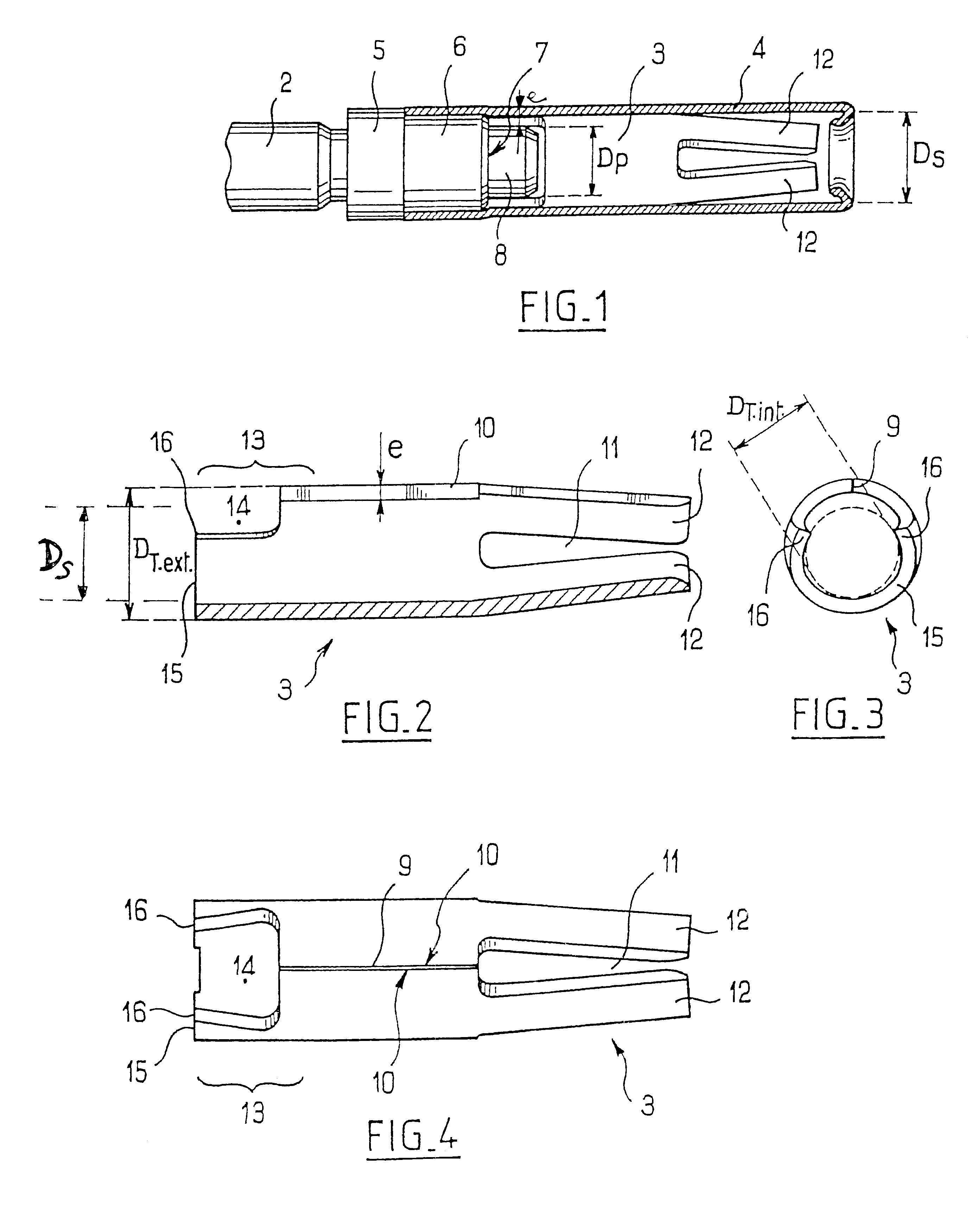
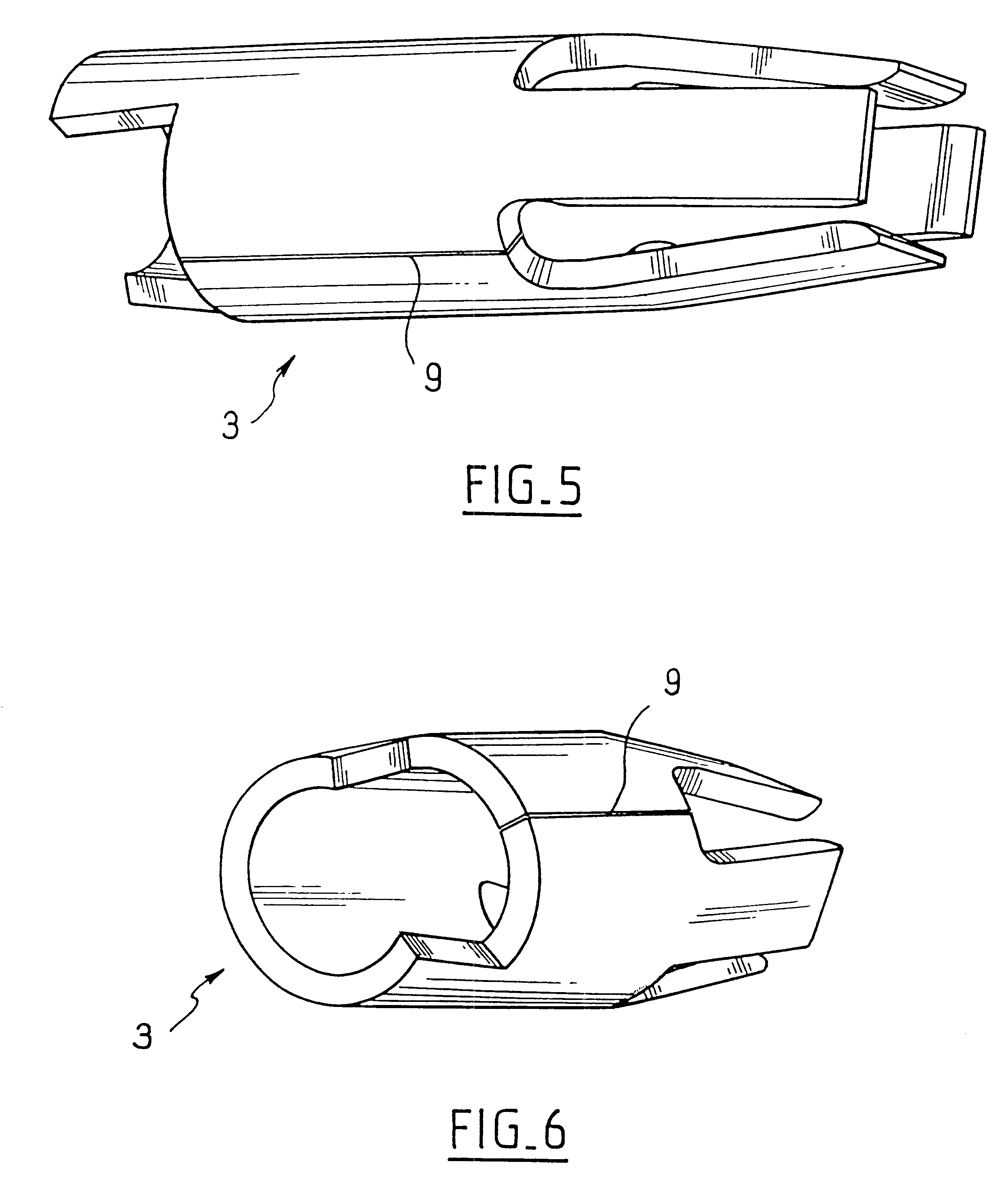
Connector element 3, which can be seen in more detail in FIGS. 2 to 6, is substantially in the form of a tube including a longitudinal slot 9.

In its closed posit...


PUM


Abstract

A contact pin for an electrical connector comprises a body, a connector element, and a sheath, the connector element being maintained in the extension of the body by being coupled with a peg projecting from the front face of the body, the sheath being disposed around the connector element and maintained on the body by clamping an annular portion of the latter. At the peg end, connector element comprises an end for coupling with said pin, conformed such that the pin cannot fit inside the cross section of said coupling end, the connector element being capable of deforming elastically to enable its coupling end to friction fit onto the pin, the thus deformed connector element being unable to fit inside the cross section of the sheath.

Description

The present invention relates to a contact pin for an electrical connector.Multi-pin electrical connectors generally comprise a large number of contact pins, each of which comprises a connecting end intended to co-operate with the connecting end of a contact pin of an associated multi-pin connector and a joining end intended to receive the lead of an electrical cable which is soldered, brazed or wrapped onto that end.Contact pins are routinely produced in two parts, namely a front part constituting the connecting end and a rear part constituting the joining end, to enable different materials with suitable elastic and plastic properties to be used.With such contact pins, a problem arises when interconnecting the front and rear parts, since said coupling must be carried out simply and rapidly and must result in good electrical contact by introducing a minimum amount of disturbance to the electrical signal transmitted by the pin.OBJECTS AND SUMMARY OF THE INVENTIONThe present invention...

Claims


Application Information

Patent Timeline
Patent Type & Authority Patents(United States)
IPC IPC(8): H01R13/11H01R43/16
CPCH01R13/11H01R43/16H01R13/187
Inventor DESPOUYS, PAUL JEAN-BERNARD
Owner RADIALL SA
Why Eureka
Try Eureka