Method and device for controlling the movement of a movable part

Inactive Publication Date: 2002-11-05
DELAVAL HLDG AB
View PDF3 Cites 23 Cited by
  • Summary
  • Abstract
  • Description
  • Claims
  • Application Information

AI Technical Summary

Problems solved by technology

A problem occurs if the robot arm is in contact with an obstacle, such as an operator or a part of an animal, which is in the path of the robot arm.

Method used


Image

  • Method and device for controlling the movement of a movable part
  • Method and device for controlling the movement of a movable part
  • Method and device for controlling the movement of a movable part

Examples


Embodiment Construction

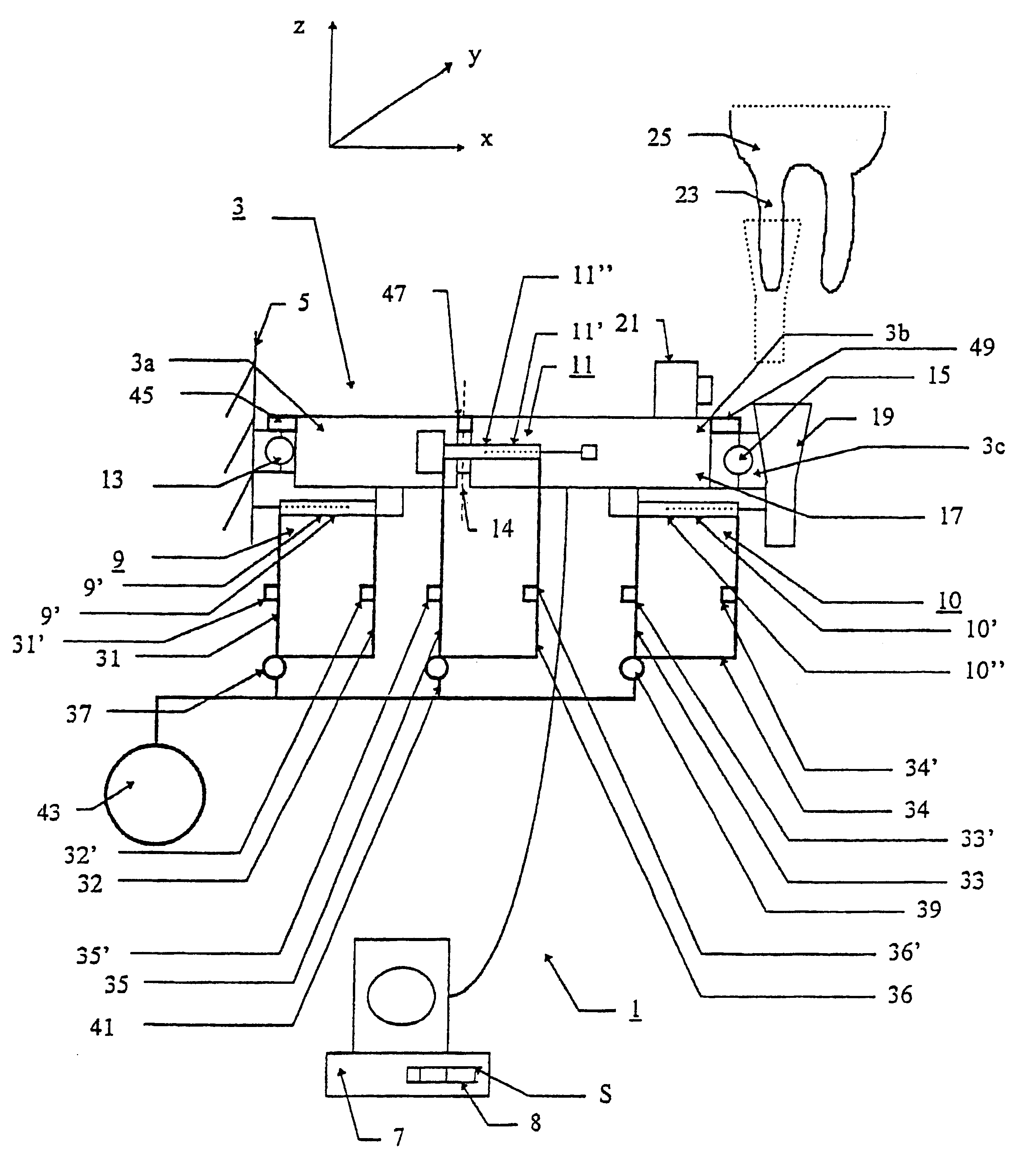
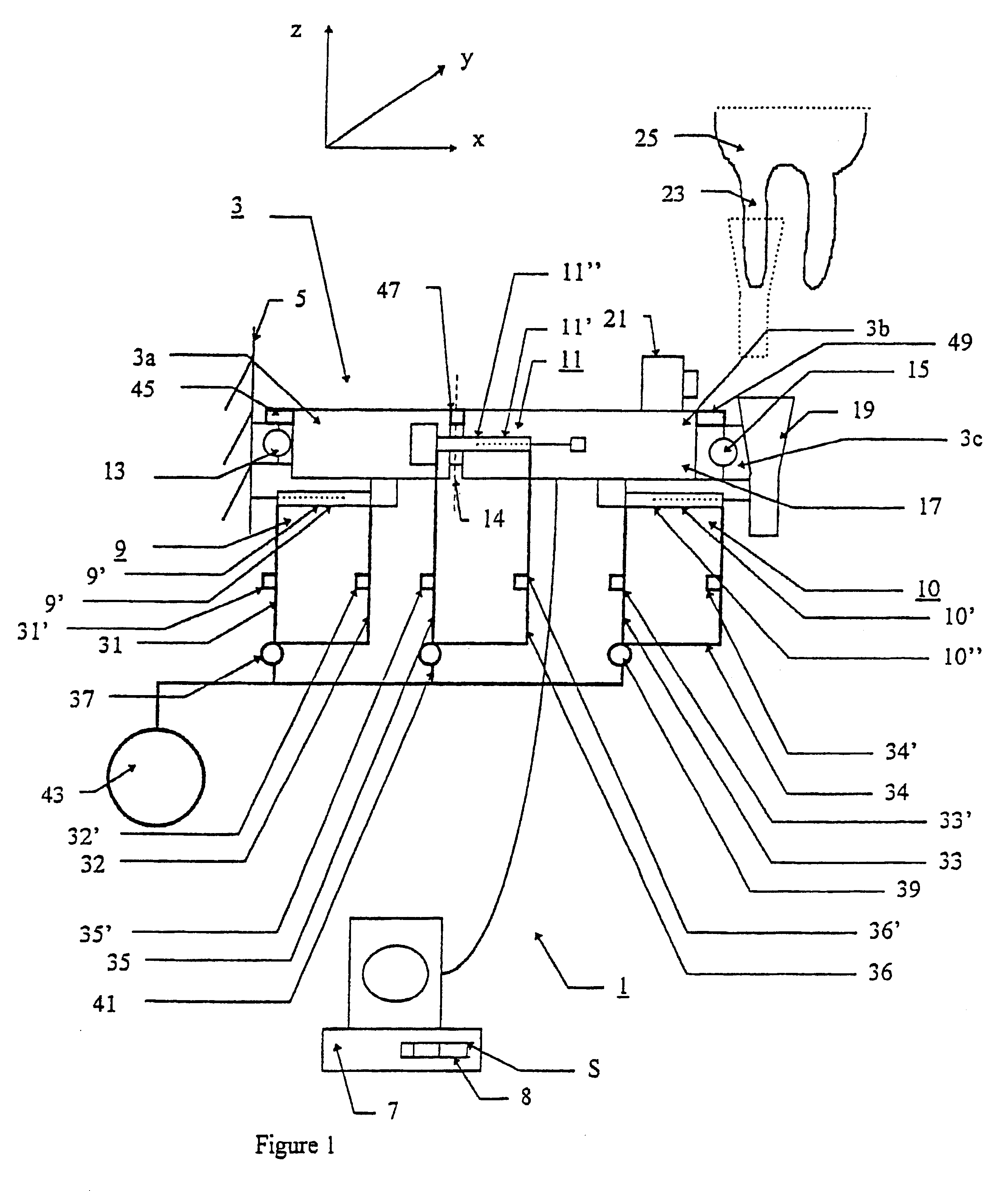
FIG. 1 shows schematically a milking robot 1 with a robot arm 3. The robot arm 3 is fixed to a frame 5 and is connected to a control means such as a computer 7. The computer 7 has a memory 8 containing operating software, which controls the movement of the robot arm as described later. The robot arm 3 is manoeuvrable in the x-, y- and z-axes by suitable actuating means. In this figure, for the sake of simplicity of illustration, only three actuating means are shown, namely pneumatic actuators 9, 10, 11 and respective hinged joints 13, 14, 15, but it is of course possible to use any suitable number and type of actuating means. Thus, the robot arm 3 can for example be provided with telescopic joints in addition to or instead of hinged joints. The robot arm 3 is provided at one end 17 with tool means, for example a washing means, brushing means or, as shown here, a teat cup 19 and sensing means like for example a camera 21. Actuators 9, 10, 11 each comprise a cylinder, 9', 10', 11' res...


PUM


Abstract

A method and device (1) for controlling the movement of a movable part such as a robot arm (3) in a milking robot (1). A control (7) controls the movement of the arm (3) from an actual position (Pxa, Pya, Pza) to a desired position (Pxd, Pyd, Pzd) A detector (45, 47, 49) detects the actual position of the robot arm (3) and transmits signals corresponding to the actual position to the control (7). The predicted position (Pxp, Pyp, PyP), that the robot arm (3) will pass through as it moves from the actual position to the desired position our model (S). The control (7) makes a comparison (S) of the actual positions of the arm (3) against to the predicted positions, and the movement of the robot arm (3) is modified if its actual position at any time differs by more than a predetermined amount from the predicted position at the same time.

Description

The present invention relates to a method and a device of the type mentioned in the preambles of the independent claims for controlling the movement of moving parts in a milking machine.DESCRIPTION OF RELATED ARTAutomatic milking machines are known in which a robot arm is used to move various attachments such as teat cups and cleaning devices from docking stations on for example the frame of the machine to working positions, for example under the udder of the animal being milked. The movement of the robot arm is controlled by a computer, which determines a desired position for the attachment and operates actuators on the arm in a controlled manner in order to bring the attachment to the desired position. The computer determines the distance in the x-, y-, z- and rotational axes between the current position and the desired position and commands each of the x-, y-, z-axes and rotational actuators to respectively extend, retract or rotate the necessary amount in order to move the robot...

Claims


Application Information

Patent Timeline
Patent Type & Authority Patents(United States)
IPC IPC(8): A01J5/017A01J5/00G05B19/19G05B19/31A01K13/00A01J7/00B25J9/10B25J9/18
CPCA01J5/0175G05B19/311G05B2219/40228G05B2219/45113Y02P90/02
Inventor NILSSONLIAO, BOHAO
Owner DELAVAL HLDG AB
Why Eureka
Try Eureka