Fuel injection valve and method for operating a fuel injection valve

a fuel injection valve and valve body technology, applied in the direction of fuel injecting pumps, electric control, machines/engines, etc., can solve the problems of too expensive and complicated arrangement of hydraulic step-up mechanisms for the purpose of temperature compensation only, and the temperature-dependent elongation of piezoelectric actuators is relatively slow,

Inactive Publication Date: 2002-11-12
ROBERT BOSCH GMBH
View PDF9 Cites 40 Cited by
  • Summary
  • Abstract
  • Description
  • Claims
  • Application Information

AI Technical Summary

Problems solved by technology

This temperature-dependent elongation of the piezoelectric actuator is, however, relatively slow compared to the actuator's actuating stroke which results in the opening of the fuel injector.
For such applications, the arrangement of a hydraulic step-up mechanism for the purpose of temperature compensatio

Method used


Image

  • Fuel injection valve and method for operating a fuel injection valve
  • Fuel injection valve and method for operating a fuel injection valve

Examples


Embodiment Construction

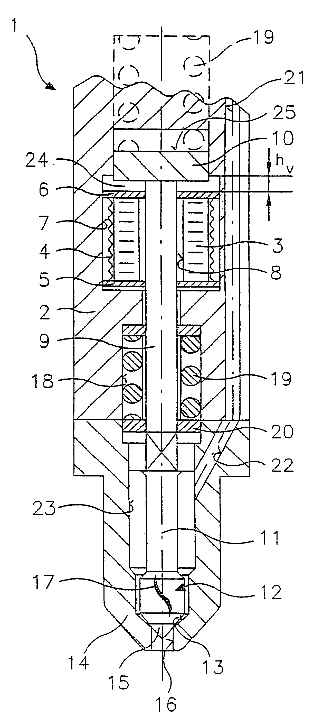
FIG. 1 shows an axial section of one embodiment of fuel injector 1 according to the present invention. Fuel injector 1 is well suited, in particular, for direct injection of fuel, in particular of gasoline, into the combustion chamber of an internal combustion engine, preferably having mixture compression and spark ignition.

A piezoelectric actuator 3, surrounded by a pre-tensioning element 4 in the form of a sleeve, is integrated in a housing body 2. Piezoelectric actuator 3 is secured between a first actuator flange 5 and a second actuator flange 6 via pre-tensioning element 4 connected to actuator flanges 5 and 6. Actuator 3, actuator flanges 5 and 6, and pre-tensioning element 4 are inserted in a cylindrical recess 7 of housing body 2. Actuator 3 is supported by housing body 2 via first actuator flange 5.

In this embodiment, actuator 3 is designed in the form of a sleeve. Both actuator 3 and actuator flanges 5 and 6 have a central opening 8, which is traversed by a valve needle 9....


PUM


Abstract

A fuel injector (1), in particular a fuel injector for fuel injection systems of internal combustion engines, has a piezoelectric or magnetostrictive actuator (3) and a valve closing body (12) which can be actuated by the actuator (3) via an actuating path (6, 24, 10, 9), the valve closing body (12) working together with a valve seat surface (13) to form a sealing seat. A gap (24) is formed in the actuating path (6, 24, 10, 9) in the non-energized rest state of the actuator (3).

Description

BACKGROUND INFORMATIONThe present invention is based on a fuel injector according to the definition of the species of Claim 1 and a method of operating a fuel injector according to the definition of the species of Claim 7.German Patent Application 195 00 706 A1 describes a fuel injector of the type defined in the main claim. In the fuel injector described in this document, a piezoelectric actuator is provided for actuating a valve needle connected to a valve closing body. The valve closing body works together with a valve seat surface to form a sealing seat. The fuel injector can be designed as either an outward-opening or an inward-opening fuel injector. The piezoelectric actuator formed by a plurality of stacked piezoelectric layers generates relatively high displacement forces, but relatively short displacement paths. Therefore, the known document proposes that a hydraulic step-up mechanism be provided to magnify the displacement path between the valve needle and the piezoelectri...

Claims


Application Information

Patent Timeline
IPC IPC(8): F02M51/06F02M63/00F02D41/20F02M61/08F02M61/16H01L41/09
CPCF02D41/2096F02M51/0603F02D2041/2044F02M61/08F02M61/163F02M61/18
Inventor BOECKING, FRIEDRICH
Owner ROBERT BOSCH GMBH
Why Eureka
Try Eureka