Rheometer

a rheometer and rheometer technology, applied in the field of rheometers, can solve problems such as arising in regard to repeatability, and achieve the effect of reducing or at least ameliorating the above disadvantages

Inactive Publication Date: 2002-11-19
STABLE MICRO SYST
View PDF12 Cites 8 Cited by
  • Summary
  • Abstract
  • Description
  • Claims
  • Application Information

AI Technical Summary

Benefits of technology

It is therefore an object of the present invention to provide a rheometer incorporating a blade which eliminates or at least ameliorates the above disadvantages.

Problems solved by technology

We have found that, although this arrangement of the prior art is generally satisfactory, some disadvantages can arise with regard to achieving repeatability when testing materials of different bulk density and rheology and particularly when comparing data derived from blades of different sizes.

Method used


Image

  • Rheometer
  • Rheometer
  • Rheometer

Examples


Embodiment Construction

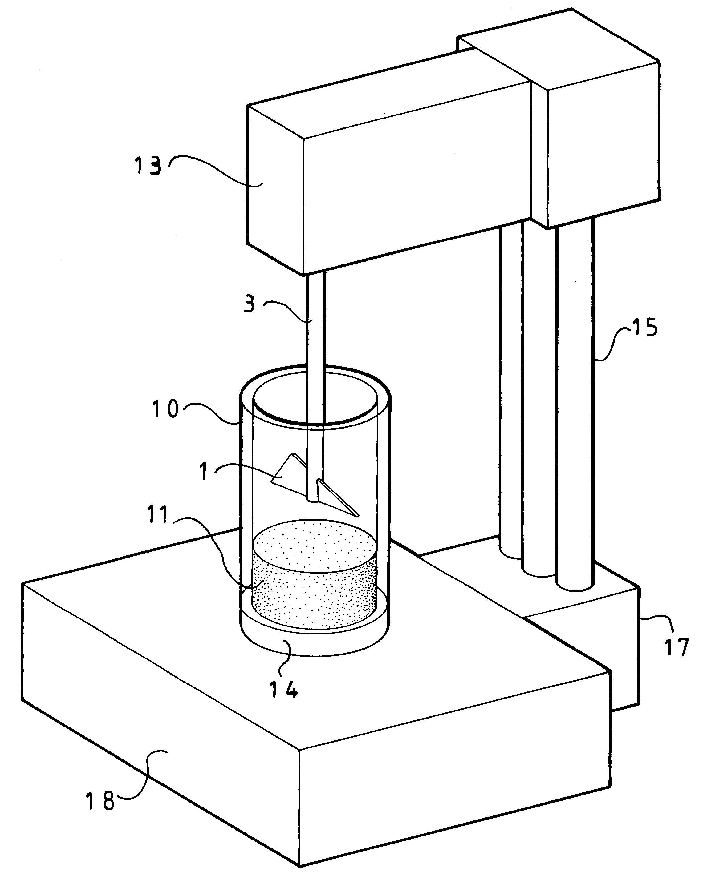
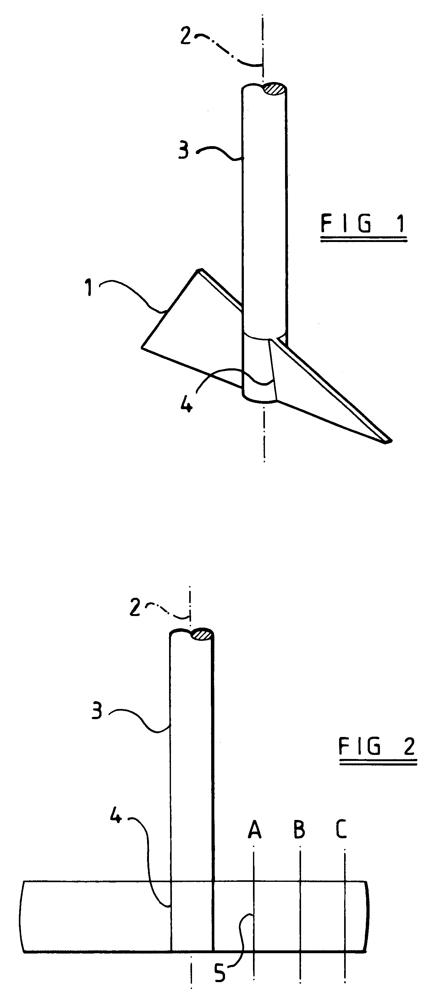
Referring to FIG. 1, a blade 1 for a rheometer is arranged to be mountable in a rheometer for rotation about an axis 2 on a shaft 3. The blade 1 has a region 4 arranged substantially at the axis of rotation 2 and such that the surface of the blade at this region 4 is substantially parallel to the axis of rotation 2. This means that the blade 1 where connected to the shaft 3 has its major surface in that region aligned with the axis of rotation 2 and the shaft 3.

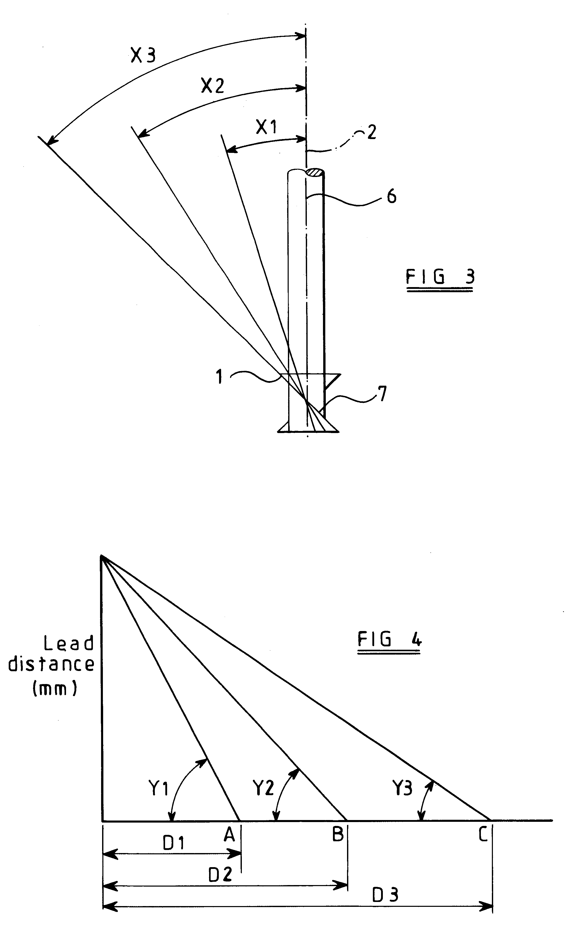
The blade 1 extending outwards from that region is of twisted form and is arranged to extend radially, that is substantially at right angles to the axis of rotation 2 and preferably horizontally when in operation in a rheometer. As illustrated in FIG. 2, this means that at any one of locations A, B, C along the blade, straight line paths 5 drawn across the blade surface perpendicular to the blade edge will be parallel to the axis of rotation 2.

As illustrated in FIG. 3, reference numeral 6 refers to a plane through and along t...


PUM

PropertyMeasurementUnit
angleaaaaaaaaaa
anglesaaaaaaaaaa
heightaaaaaaaaaa

Abstract

A rheometer incorporates a blade (1) mounted for rotation about an axis (2). The blade is of twisted form such that it has first and second regions. A first region of the blade (1) substantially at the axis of rotation (2) has a first angle formed by its surface with respect to a plane perpendicular to the axis of rotation such that the surface of the blade in the first region extends substantially parallel to the axis of rotation. A second region of the blade spaced from the axis of rotation has a second angle, different to the first angle, formed by its surface with respect to the plane perpendicular to the axis of rotation.

Description

This invention relates to a rheometer incorporating a blade mounted for rotation about an axis.BACKGROUND TO THE INVENTIONRheometers are well known and used in a wide variety of chemical and material processing industries for assessing characteristics, such as flow characteristics, of materials such as powders, liquids and semi-solids such as pastes, gels, ointments and the like.DESCRIPTION OF PRIOR ARTOne particular rheometer is described in WO-A-9736162 in which blades extend substantially radially from a rotor shaft and are disposed at an angle relative to the axis of the shaft. The blades may be of twisted form; however the blade is at an angle over its entire length, relative to the axis of the shaft.We have found that, although this arrangement of the prior art is generally satisfactory, some disadvantages can arise with regard to achieving repeatability when testing materials of different bulk density and rheology and particularly when comparing data derived from blades of di...

Claims


Application Information

Patent Timeline
Patent Type & Authority Patents(United States)
IPC IPC(8): G01N11/10G01N11/14G01N33/00
CPCG01N11/14G01N2033/0091
Inventor ILES, CHRISTOPHER MARTINBATESON, IAN DAVIDWALKER, JAMES ALFRED
Owner STABLE MICRO SYST
Why Eureka
Try Eureka