Tandem six port 3:1 divider combiner

a technology of divider combiner and divider, which is applied in the direction of coupling devices, electrical devices, waveguides, etc., can solve the problems of poor active return loss, limited power performance of wilkinson three-way divider/combiner, and inability of n-way combiners to provide such swr performan

Inactive Publication Date: 2002-11-19
RAYTHEON CO
View PDF6 Cites 43 Cited by
  • Summary
  • Abstract
  • Description
  • Claims
  • Application Information

AI Technical Summary

Problems solved by technology

N-way combiners are not known to provide such SWR performance.
It is highly reactive at the second harmonic of the operating frequency and has poor active return loss, which is not acceptable for C-class amplifiers.
The Wilkinson three-way divider / combiner has limited power performance and requires a tri-dimensional resistive balancing circuit.
That is, the Wilkinson divider / combiner has no equal mismatch canceling, modest isolation, no high power capability and is non-planar (3D).
In addition, the fringe fields around the balancing resistors increase the insertion loss.
Good power capability and isolation are offered by the Gysel combiner, but this design does not have the important property of identical mismatch canceling.
In addition. the Gysel combiner is mismatched at the second harmonic.
Its complex design requires a large printed wiring board (PWB) area.
The result is a large, lossy device in microstrip, which is difficult to implement in planar artwork.
The chain combiner can offer good performance but the 3 dB and 4.77 dB overlay couplers required, and the registration requirements thereof, limit the peak power capability and can not be integrated in a microstrip layout.
It would also require a special substrate thickness which would be unacceptable in the high power microwave application.
The star divider has not proven to be feasible for this application.
Various other (star divider derived) planar geometries have been explored to create a 1:N divider / combiner but the performances obtained are not satisfactory when compared to what is necessary in a microwave C-class amplifier.

Method used


Image

  • Tandem six port 3:1 divider combiner
  • Tandem six port 3:1 divider combiner
  • Tandem six port 3:1 divider combiner

Examples


Embodiment Construction

Illustrative embodiments and exemplary applications will now be described with reference to the accompanying drawings to disclose the advantageous teachings of the present invention.

While the present invention is described herein with reference to illustrative embodiments for particular applications, it should be understood that the invention is not limited thereto. Those having ordinary skill in the art and access to the teachings provided herein will recognize additional modifications, applications, and embodiments within the scope thereof and additional fields in which the present invention would be of significant utility.

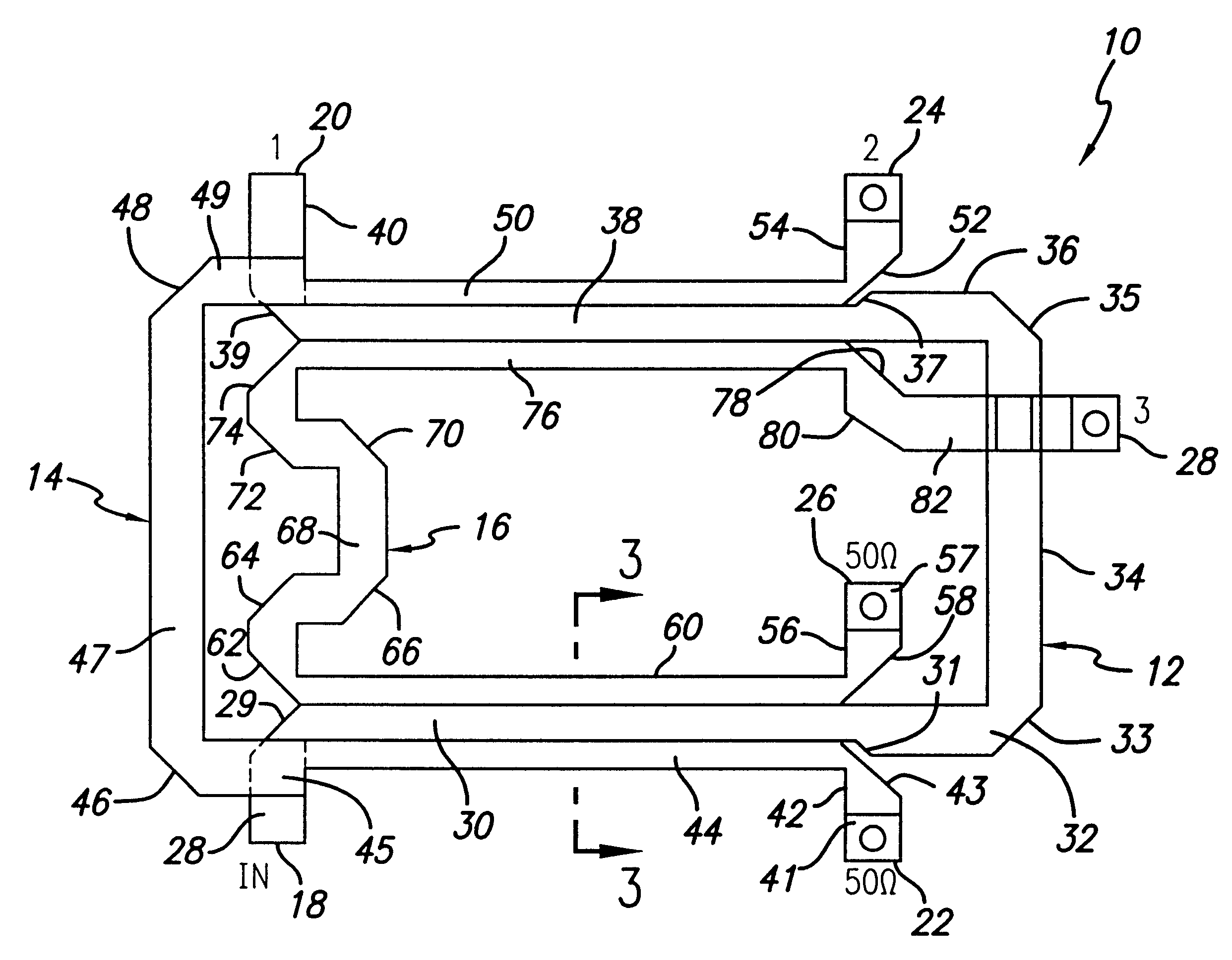
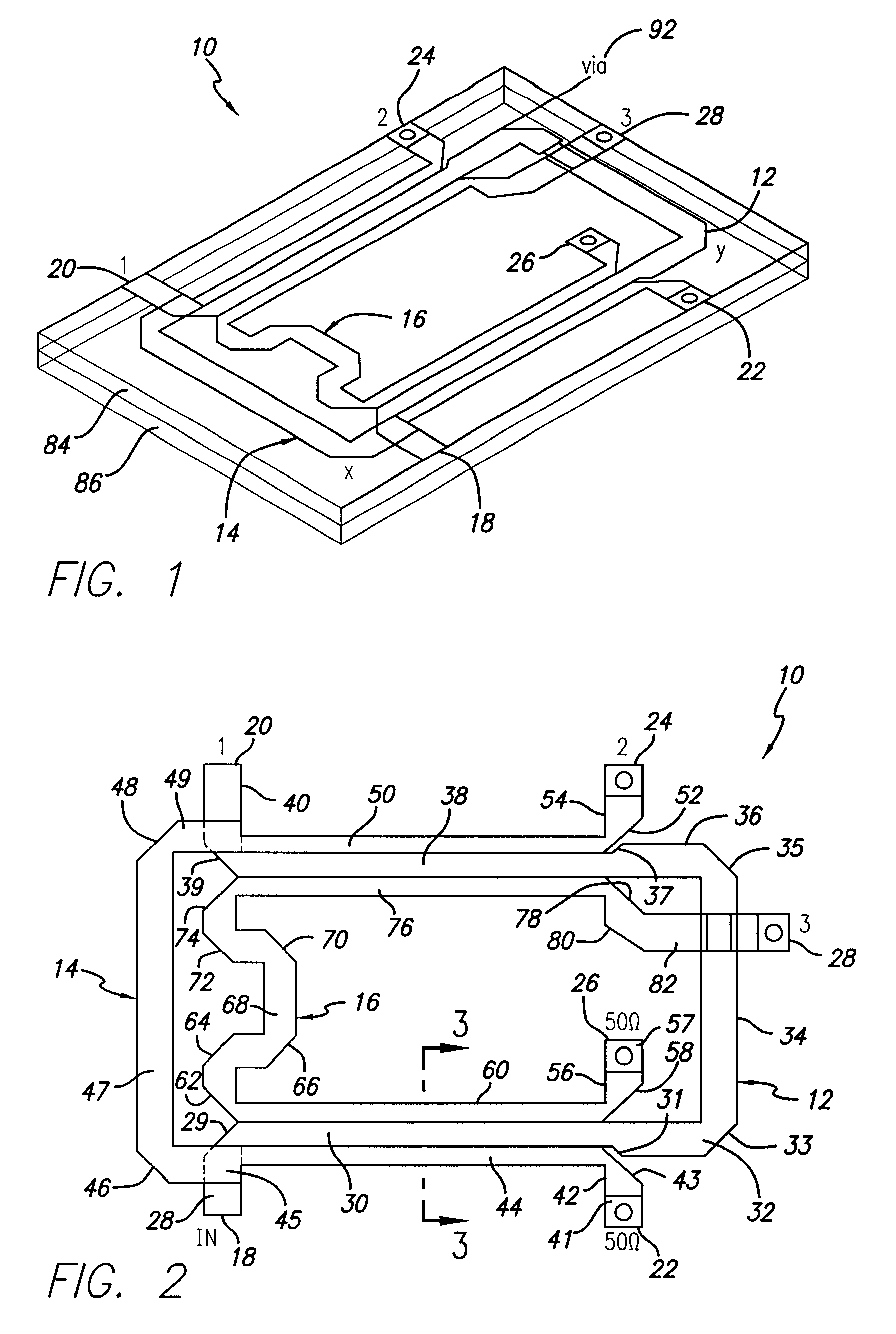
FIG. 1 is a perspective view of an illustrative implementation of the power divider and combiner of the present invention. As discussed more fully below, the new 3:1 coupler is formed by connecting in tandem two six port structures (three-line directional couplers, having a much looser coupling than -4.77 dB), interconnected with three equal electrical length, 5...


PUM


Abstract

A six port 3:1 power divider and combiner. The inventive divider / combiner includes first, second and third weakly coupled transmission lines. The first transmission line provides first and second ports at first and second ends thereof, respectively. The second transmission line provides third and fourth ports at first and second ends thereof, respectively and the third transmission line provides fifth and sixth ports at first and second ends thereof, respectively. In the illustrative embodiment, the first, second and third transmission lines are coupled to provide equal outputs at said second, fourth and sixth ports in response to an application of a signal at the first port. The first second and third conductors may be implemented with coaxial, stripline or microstrip type transmission lines. The looser coupling is very beneficial, especially in microstrip, to obtain high power capability and a manufacturable circuit. In an illustrative 3:1 divider / combiner implementation, the coupling arrangement provides a voltage coupling coefficient x equal to 0.325057. Consequently, the first, second and third coupling lines have a relative coupling value of approximately -10 decibels. In the best mode, the first, second and third coupling lines have a relative coupling value of -9.76 decibels.

Description

1. Field of the InventionThe present invention relates to power dividers and combiners. More specifically, the present invention relates to high power, large bandwidth power divider and combiners operating at S-band for driving, C-class amplifiers.2. Description of the Related ArtPower dividers are used to direct microwave radio frequency (RF) power from one source to two or more outputs. Likewise, power combiners are used to combine power from two or more sources to provide one output. Currently, the most widely used coupler in the RF field is the overlay hybrid four port Coupler. The overlay hybrid four port coupler is a two-way combiner having two inputs, each of which communicates with two outputs. It is an `overlay` coupler because one or more of the conductors thereof couple energy to an adjacent conductor by physically overlaying the adjacent conductor. The overlay hybrid four port coupler is widely used because it improves the voltage standing wave ratio (VSWR) of a signal n...

Claims


Application Information

Patent Timeline
Patent Type & Authority Patents(United States)
IPC IPC(8): H01P5/12
CPCH01P5/12
Inventor CATOIU, MIRON
Owner RAYTHEON CO
Why Eureka
Try Eureka