Tread pattern which reduces the running noise of a tire

a tread pattern and tire technology, applied in the field of treads for tires, can solve the problem of increasing the running noise of tires equipped with treads

Inactive Publication Date: 2002-11-26
MICHELIN RECH & TECH SA
View PDF16 Cites 17 Cited by
  • Summary
  • Abstract
  • Description
  • Claims
  • Application Information

AI Technical Summary

Problems solved by technology

Unfortunately, this arrangement results in an increase in the traveling noise of the tire equipped with a tread provided with such a tread patter

Method used


Image

  • Tread pattern which reduces the running noise of a tire
  • Tread pattern which reduces the running noise of a tire

Examples


Embodiment Construction

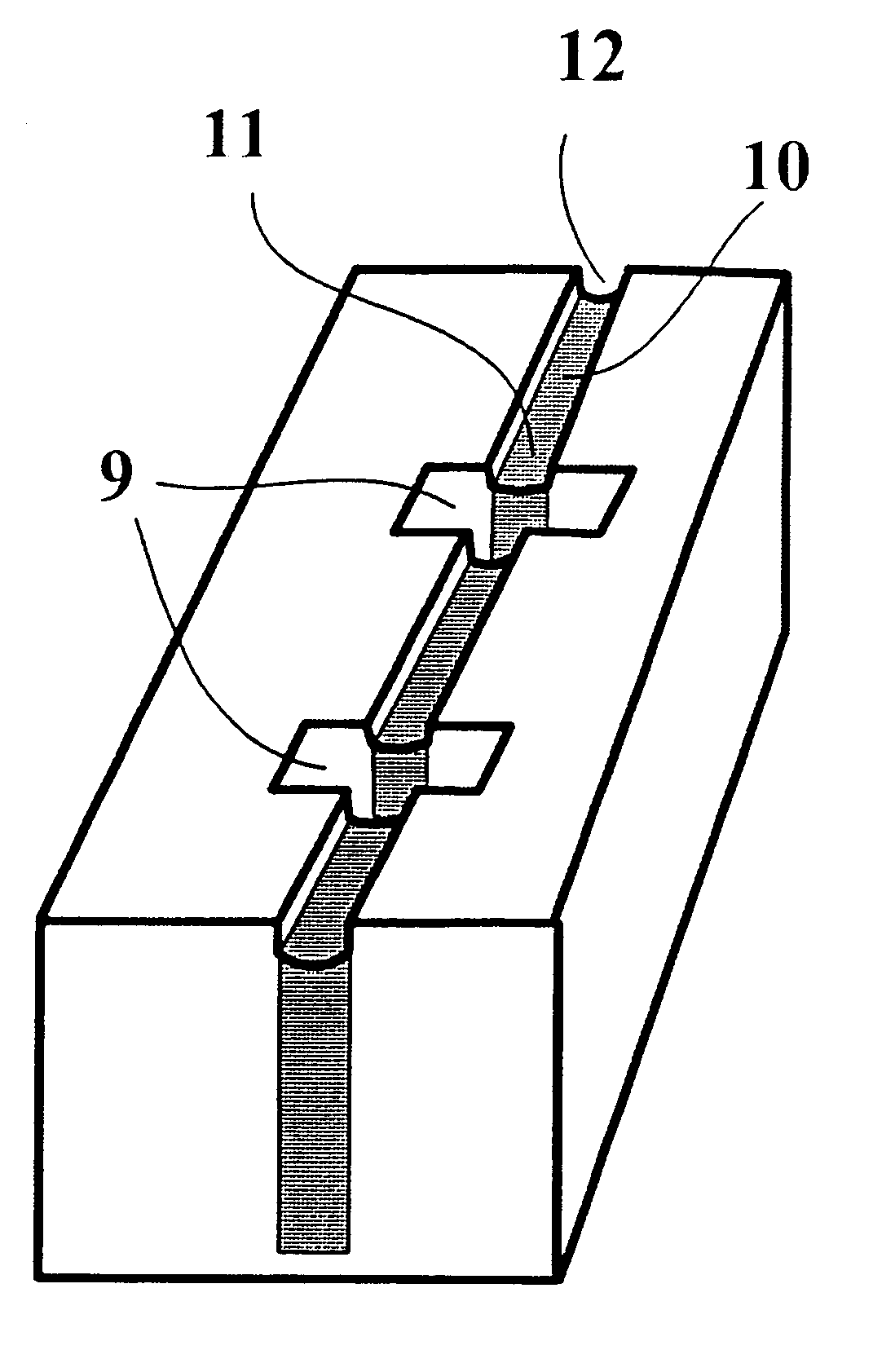
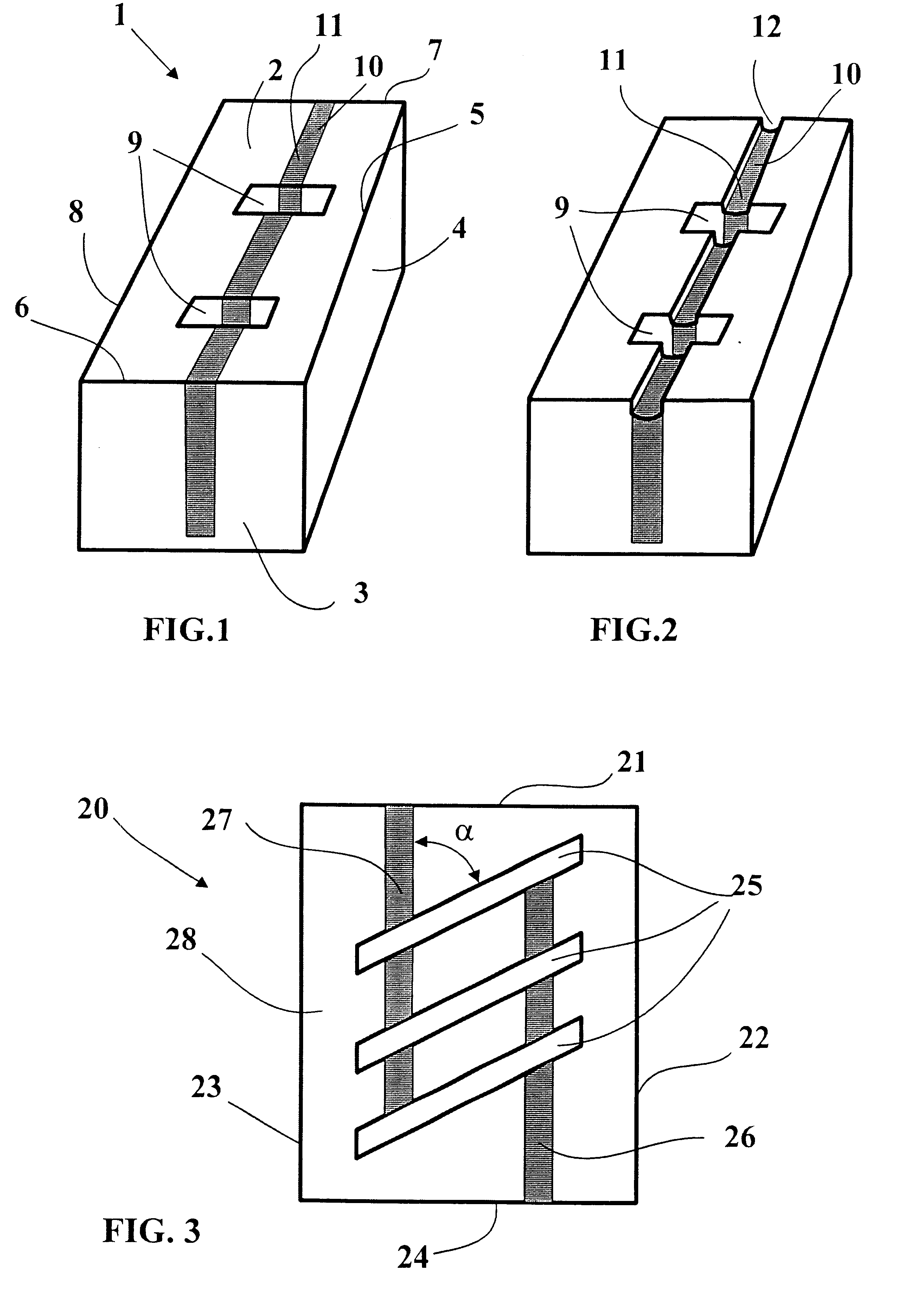
In FIG. 1, there can be seen a block 1 of a tread pattern for a tire; this block is in the form of a parallelepiped defined by four lateral faces (only two of these faces 3, 4 being visible in this figure) and an upper or outer face 2 corresponding to the face of the block which comes into contact with the ground during travel of the tire. The intersection of the lateral faces with the upper face forms ridges 5, 6, 78. This block comprises two blind incisions 9, that is to say, ones which do not intersect any of the ridges defining the upper face of the block 1, whatever the level of wear of said block. These two incisions 9 have rectilinear traces which are substantially parallel to each other and are of average orientation equal to the orientation of the ridges 6 and 7.

Furthermore, the block 1 comprises a cutout 10, the opposing walls of which are connected mechanically by a filler material 11 which completely occupies the volume of this cutout 10, said cutout 10 having an average...


PUM


Abstract

A tread pattern for a tire, the tread pattern being formed by elements in relief defined by grooves, some of these elements in relief being provided with at least one blind incision, that is to say, one which does not open into the grooves. These elements in relief include at least one cutout which opens into at least one groove defining these elements, and such that, on the running surface, each blind incision crosses at least one open-ended cutout of the same element, whatever the level of wear of the tire. Each of these open-ended incisions has a depth substantially equal to the depth of the blind incisions which it crosses and is filled with a filler material, the filler material having the characteristic of being gradually eliminated under the action of frictional contact with the ground during travel to form a channel of low depth which enables the air trapped in the blind incisions to escape.

Description

BACKGROUND OF INVENTIONThe invention relates to the field of treads for tires, and in particular to treads, the elements in relief (blocks or ribs) of which are provided with incisions.It is known to provide the tread of a tire, whether the latter be intended to be fitted on a passenger vehicle or on a heavy vehicle, with a tread pattern in order to obtain satisfactory adhesion performance, particularly on ground which has been made slippery by the presence of a liquid. A tread pattern comprises blocks (sections of rubber defined by grooves) and / or ribs (sections of rubber defined by two grooves extending substantially in the same direction) defined by grooves formed by molding into the thickness of the tread.In order to improve the adhesion performance of a tread, it is known to use a large number of incisions made on the tread pattern elements either during the molding of said tread pattern or after molding and vulcanization of said tread."Groove" is understood to mean a cutout of...

Claims


Application Information

Patent Timeline
IPC IPC(8): B60C11/12B60C11/14B60C1/00B60C11/11B60C11/18B60C11/00
CPCB60C1/0016B60C11/11B60C11/12B60C11/18B60C11/124B60C2011/1254B60C2011/1245Y10S152/03
Inventor BRUANT, REMI
Owner MICHELIN RECH & TECH SA
Why Eureka
Try Eureka