
Projector having a light shielding member

a technology of light shielding member and projector, which is applied in the field of projectors, can solve the problems of excessive heat generation of modulation device for modulating blue luminous flux, likely to be produced gaps in fixed parts, and deterioration of image quality projected on the screen

Inactive Publication Date: 2002-12-03
SEIKO EPSON CORP
View PDF5 Cites 41 Cited by
  • Summary
  • Abstract
  • Description
  • Claims
  • Application Information

AI Technical Summary

Benefits of technology

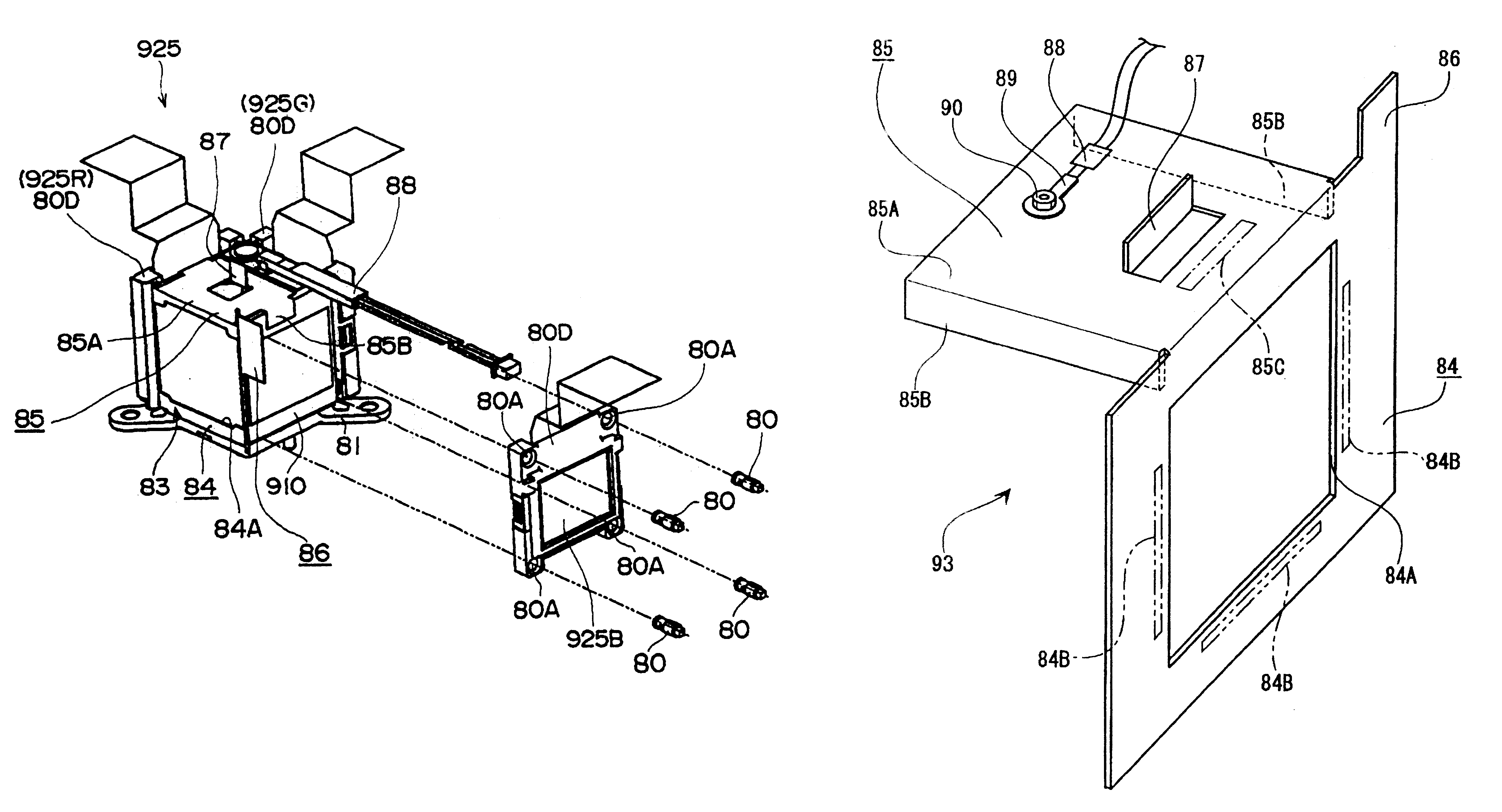
According to the present invention, the light shielding member shields leakage light from the gaps between the optical modulation device and the prism toward the projection lens side, whereby only the luminous fluxes emitted by the prism are applied to the projection lens. Therefore, the quality of projected images does not deteriorate when reducing the size.
With this arrangement, leakage light from the lower part of the prism can be shielded, whereby only the luminous fluxes emitted by the prism are applied to the projection lens. Therefore, the quality of projected images does not deteriorate when the size is reduced.

Problems solved by technology

In the POP structure, gaps are likely to be produced in the fixed parts because the optical modulation devices and the prism are fixed to each other at a predetermined distance from each other.
There is a problem in that the quality of images projected on a screen deteriorates when leakage from the light beams is applied to the projection lens.
Therefore, a modulation device for modulating the blue luminous flux is likely to heat up excessively.
When an opening is formed in the light shielding member through which the light beams are to be emitted by the prism, and the opening is not disposed at a predetermined position, there is a risk of deteriorating the quality of projected images by cutting away a part of the luminous flux emitted by the prism.

Method used


Image

  • Projector having a light shielding member
  • Projector having a light shielding member
  • Projector having a light shielding member

Examples


Embodiment Construction

Embodiments according to the present invention are described below with reference to the drawings.

(1) General Configuration of the Device

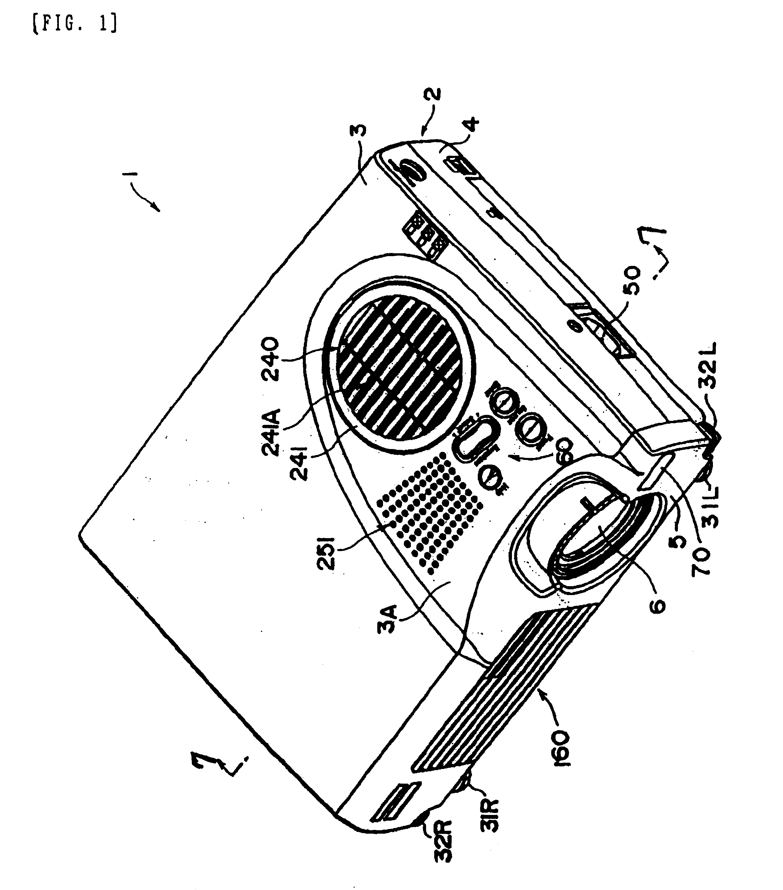
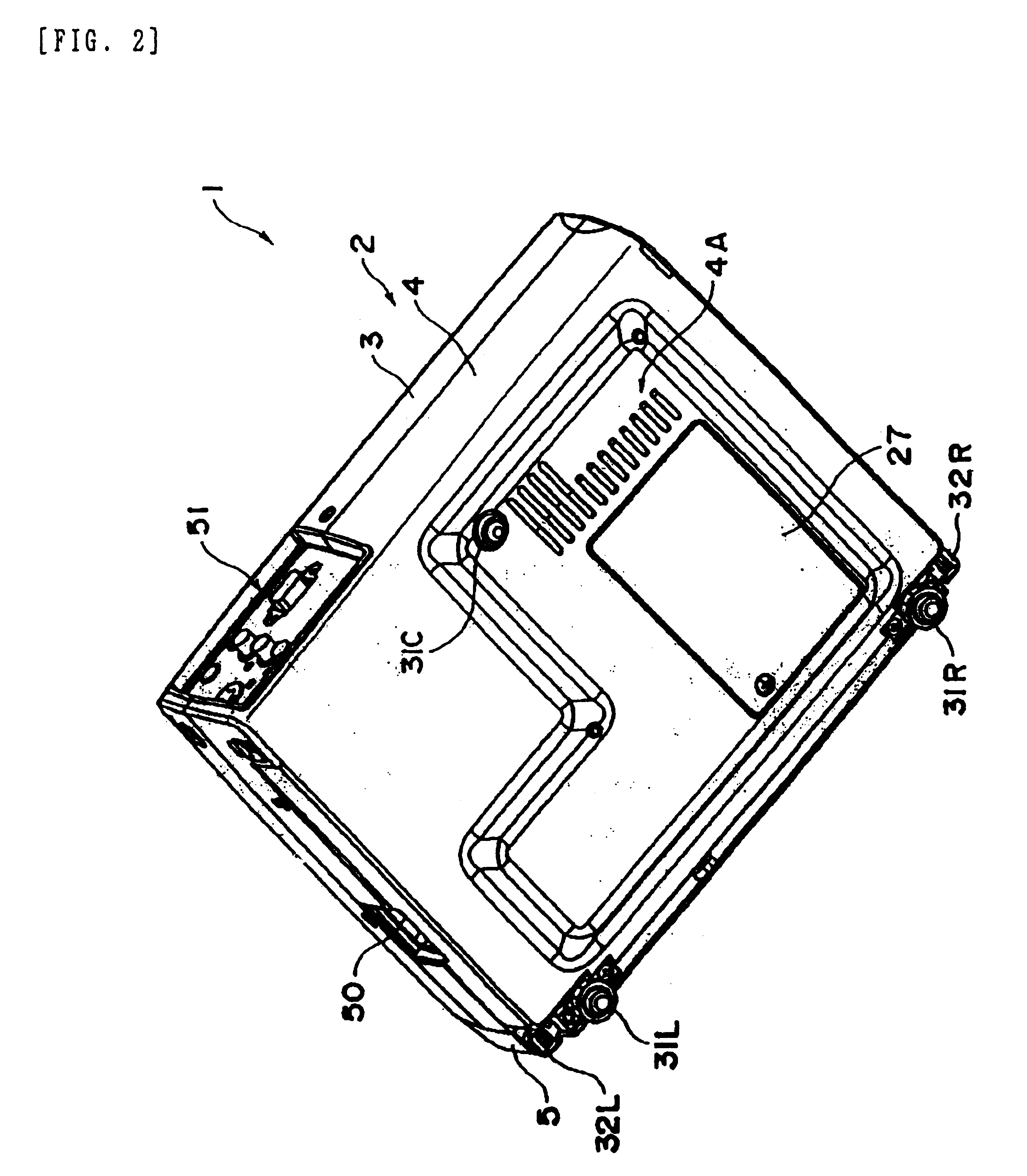
FIGS. 1 and 2 are schematic perspective views of a projector 1 according to the present embodiment. FIG. 1 is a perspective view of the projector 1 from the upper side, and FIG. 2 is a perspective view thereof from the bottom.

The projector 1 is of a type in which a luminous flux emitted by a light source device as a light source is split into three luminous fluxes of the primary colors which are red (R), green (G), and blue (B). Each colored luminous flux is transmitted through and modulated, in accordance with image data, by a liquid crystal panel forming a modulation system. The modulated luminous fluxes of each color are synthesized by a crossed dichroic prism, and the synthesized fluxes are displayed enlarged on a projection area through a projection lens 6. Each component unit is received in an outer casing 2. The projection lens 6 is disposed...


PUM

PropertyMeasurementUnit
distanceaaaaaaaaaa
luminous fluxesaaaaaaaaaa
luminous fluxaaaaaaaaaa

Abstract

To provide a projector in which the quality of projected images does not deteriorate when the size of the projector is reduced. A light shielding member for shielding leakage light from gaps between each liquid crystal panel, and a crossed dichroic prism toward a projection lens side is provided. The leakage light from the gaps between each liquid crystal panel and the crossed dichroic prism can be shielded, and only the luminous flux emitted by the crossed dichroic prism can be applied to the projection lens, whereby the quality of projected images does not deteriorate when the device is reduced in size.

Description

1. Field of InventionThe present invention relates to a projector including optical modulation devices for modulating a plurality of colored light beams in accordance with image data, a prism for combining the modulated luminous fluxes modulated by the optical modulation devices, and a projection lens for enlarging and projecting the light beams combined by the prism.2. Description of Related ArtHitherto, projectors have been used which include three optical modulation devices for modulating a plurality of colored light beams in accordance with image data, a crossed dichroic prism for combining the light beams modulated by the three optical modulation devices, and a projection lens for enlarging and projecting the light beams combined by the prism.The projectors are widely used for multimedia presentations at public meetings, such as conferences, academic meetings, and exhibitions. The projector is brought to the conference room, as needed, and is moved to another place after the us...

Claims


Application Information

Patent Timeline
Patent Type & Authority Patents(United States)
IPC IPC(8): H04N9/31G02F1/13G03B21/00G03B21/16G09F9/00H04N5/74
CPCH04N9/3105H04N9/3144H04N9/3197
Inventor FUJIMORI, MOTOYUKI
Owner SEIKO EPSON CORP
Learn More