
Power station switch with a radiator/heat-exchanger

a technology of power station switch and radiator, which is applied in the direction of air-break switch, high-tension/heavy-dress switch, substation/switching arrangement details, etc., can solve the problem of switch cost, achieve the effect of reducing the cost of making the switch, facilitating heat exchange, and reducing the cost of such a switch

Inactive Publication Date: 2002-12-10
ALSTOM TECH LTD
View PDF10 Cites 9 Cited by
  • Summary
  • Abstract
  • Description
  • Claims
  • Application Information

AI Technical Summary

Benefits of technology

The object of the invention is to propose a solution for reducing the cost of such a switch fitted with a radiator / heat -exchanger.
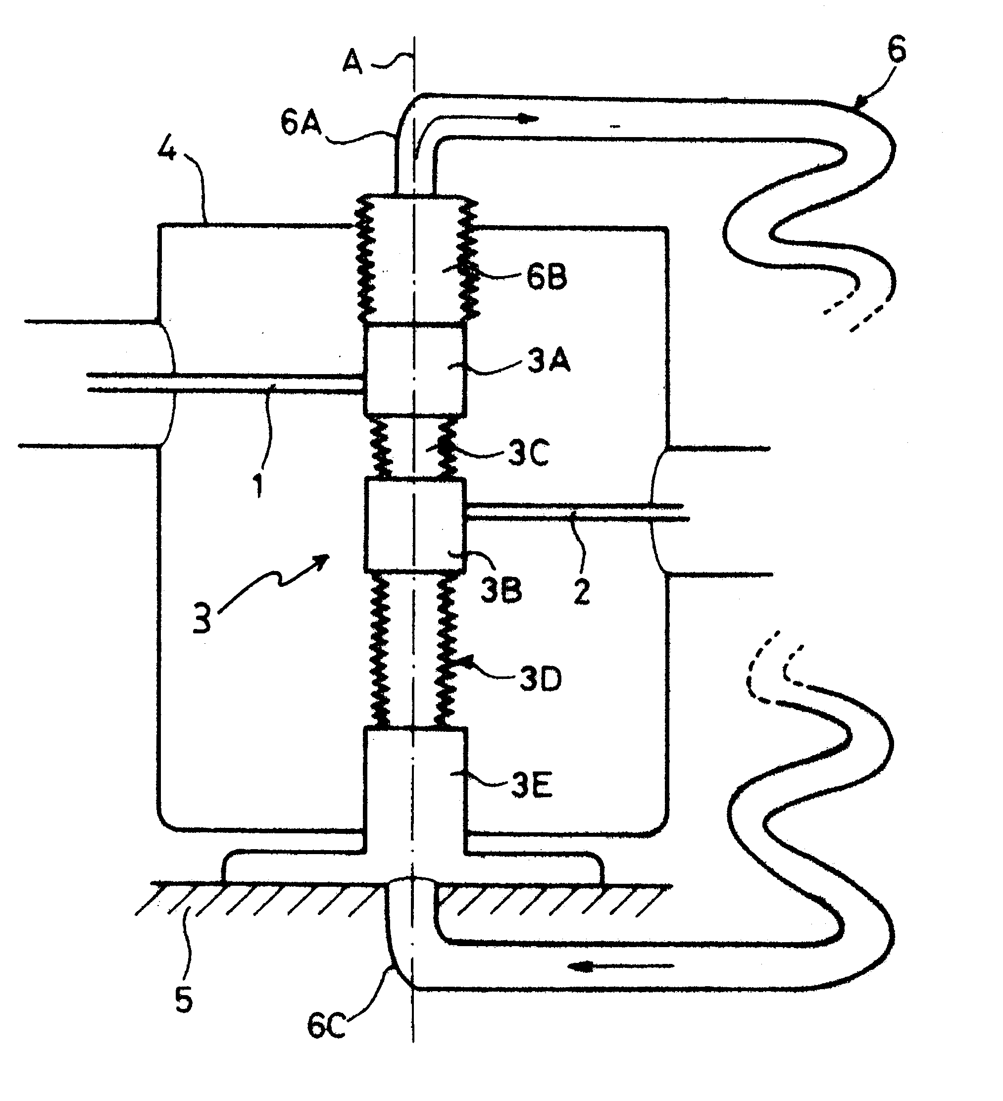
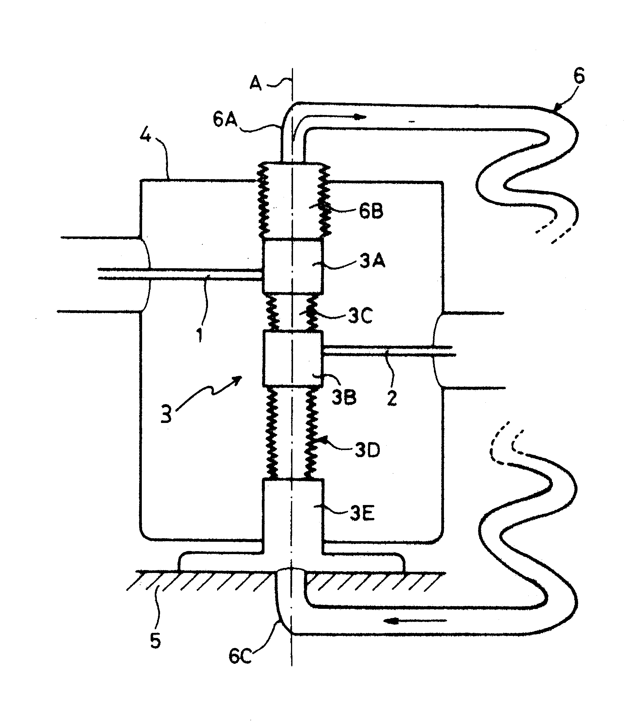
To this end, the invention provides a power station switch having high nominal current, the switch comprising a break chamber containing a dielectric gas under pressure and mounted inside a protective sheath, and a radiator / heat-exchanger situated outside said sheath and connected to said break chamber and in which said gas under pressure is put into continuous circulation, wherein said gas under pressure as cooled in the radiator / heat-exchanger is returned to the break chamber via a metal case of the break chamber that is designed to be grounded. With this arrangement, the connection of the radiator / heat-exchanger to the break chamber requires the use of a single hollow insulator instead of two as in the prior art, thereby reducing the cost of making the switch. The case that is for grounding is typically the case which has installed therein the mechanism for driving the contacts of the break chamber.
In a particular embodiment of a switch of the invention, the break chamber extends axially along a vertical direction and has at its bottom end a bottom metal case for grounding and at its top end a top metal case connected to said radiator / heat-exchanger via a hollow insulator forming an insulating bushing. This in-line disposition of the connections between the outlet tube from the radiator / heat-exchanger, the bottom metal case of the break chamber, the top metal case of the break chamber, the hollow insulator forming an insulating bushing, and finally the inlet tube of the radiator / heat-exchanger, favors natural convection to drive circulation of the gas under pressure from the break chamber to the radiator / heat-exchanger and from the radiator / heat-exchanger to the break chamber along a vertical axis, and thus favors heat exchange. In addition, this disposition contributes to increasing the draw height for natural convection, thereby enhancing the speed at which the gas under pressure circulates in the radiator / heat-exchanger and in the break chamber.

Problems solved by technology

The number of insulators used in that arrangement is an important factor in the cost of the switch.

Method used


Image

  • Power station switch with a radiator/heat-exchanger
  • Power station switch with a radiator/heat-exchanger

Examples


Embodiment Construction

Inlet and outlet conductors 1 and 2 of the switch are disposed horizontally in this embodiment while the break chamber 3 is disposed vertically. The break chamber 3 with the conductors 1 and 2 are disposed in a protective metal sheath 4 having a general flow of cooling air for the conductor 1 and 2 passing therethrough.

The break chamber has a top metal case 3A at its top end in which there is disposed, in particular, a fixed contact which is electrically connected to the inlet conductor 1, and an intermediate metal case 3B in which there is disposed, in particular, a moving contact electrically connected to the outlet conductor 2. The case 3B is connected to the case 3A by a hollow insulator 3C. The break chamber further includes, at its bottom end, a bottom metal case 3E containing the device for driving the moving contact. The case 3E is connected to the case 3B by a hollow insulator 3D. The cases 3A, 3B, and 3E, and the hollow insulators 3C and 3D are in alignment along the axis ...


PUM


Abstract

A power station switch having high nominal current, the switch comprising a break chamber containing a dielectric gas under pressure and mounted inside a protective sheath which may optionally carry a general flow of cooling air, and a radiator / heat-exchanger situated outside said sheath and connected to said break chamber in which said gas under pressure is put into continuous circulation. Said gas under pressure as cooled in the radiator / heat-exchanger is returned to the break chamber via a metal case of the break chamber that is designed to be grounded.

Description

The present invention relates to a power station switch having high nominal current, the switch comprising a break chamber containing a dielectric gas under pressure and mounted inside a protective sheath which may optionally carry a general flow of cooling air, and a radiator / heat-exchanger situated outside said sheath and connected to said break chamber in which said gas under pressure is put into continuous circulation.Such a switch is known in particular from French patent document No. 2 199 182. In that known switch, the radiator / heat-exchanger is connected to the break chamber via two hollow support insulators which extend radially from the break chamber. Other hollow insulators for grounding also support the break chamber in the sheath. The number of insulators used in that arrangement is an important factor in the cost of the switch.OBJECT AND SUMMARY OF THE INVENTIONThe object of the invention is to propose a solution for reducing the cost of such a switch fitted with a rad...

Claims


Application Information

Patent Timeline
IPC IPC(8): H01H9/00H01H9/52H02B1/00H02B1/56H01H33/02H01H33/56
CPCH01H9/52H02B1/56H01H33/56H01H2009/526
Inventor BIQUEZ, FRAN.CEDILLA.OISWILLIEME, JEAN-MARC
Owner ALSTOM TECH LTD
Learn More