Polyphase transverse flux motor

a technology of transverse flux and motor, applied in the direction of synchronous machines with stationary armatures and rotating magnets, magnetic circuit shapes/forms/construction, electrical apparatus, etc., can solve the problems of difficult manufacturing and difficult implementation of transverse flux machines in the pas

Inactive Publication Date: 2002-12-10
FISHER & PAYKEL APPLIANCES LTD
View PDF3 Cites 78 Cited by
  • Summary
  • Abstract
  • Description
  • Claims
  • Application Information

AI Technical Summary

Problems solved by technology

Transverse flux machines have in the past been difficult to implement because standard core lamination techniques do not easily permit the three dimensional. magnetic flux flow required in transverse flux machines.
Proposals for polyphase machines usually involve complex geometries which lead to difficulties in manufacture.

Method used


Image

  • Polyphase transverse flux motor
  • Polyphase transverse flux motor
  • Polyphase transverse flux motor

Examples


Embodiment Construction

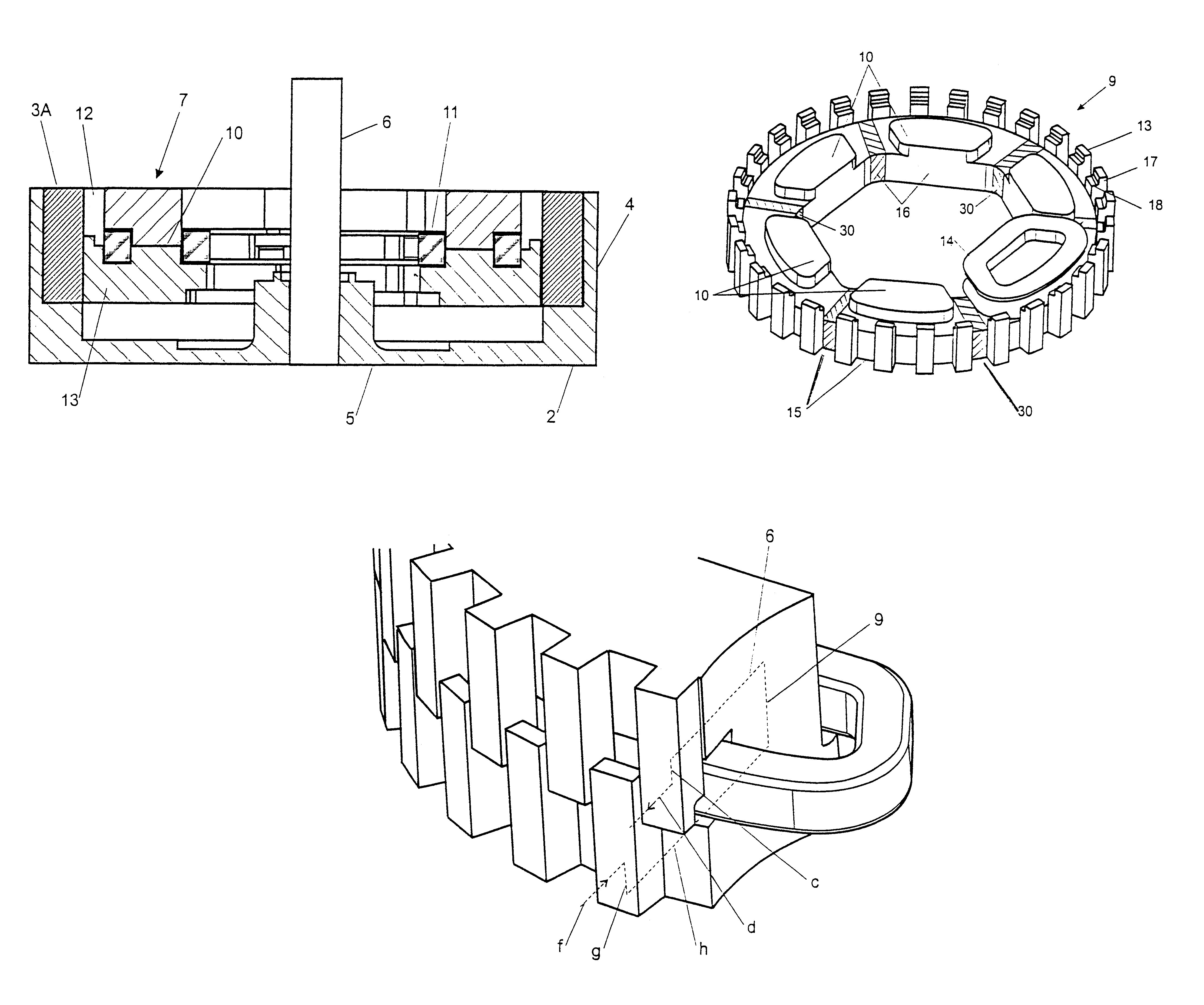
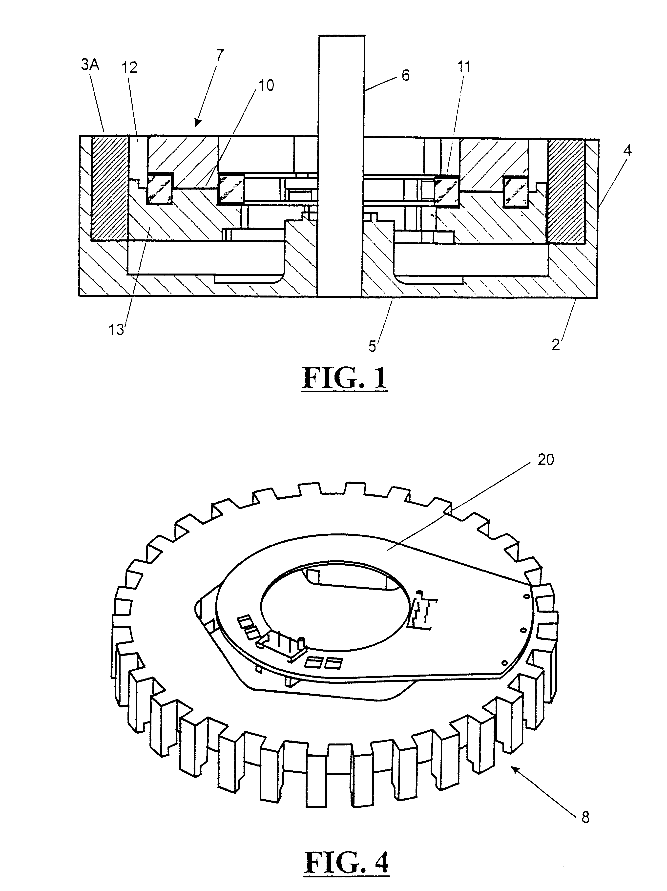
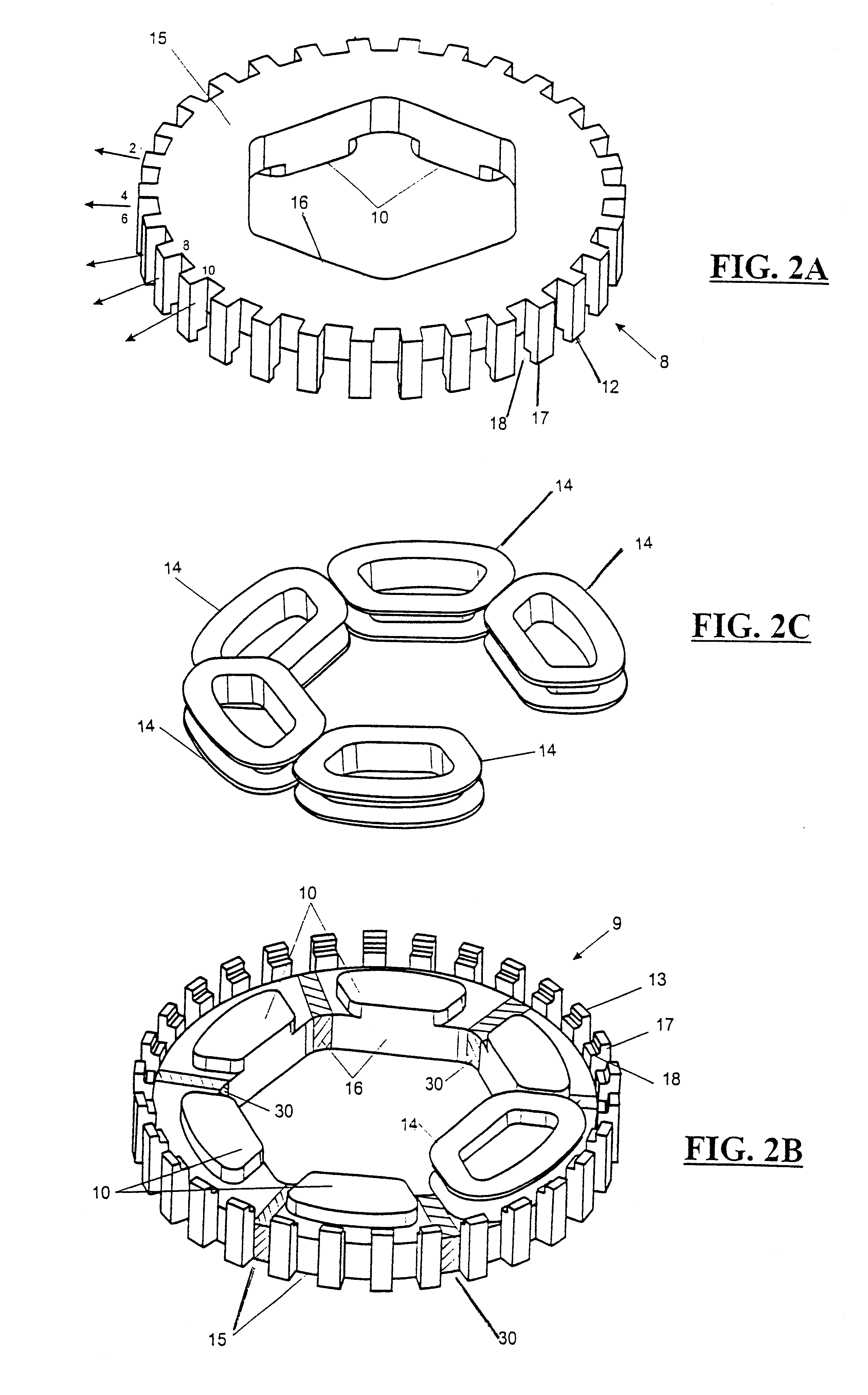
In one preferred form of the invention the rotor 2 is located externally of the stator 7 as indicated in FIG. 1. As is mentioned later a variety of known rotor configurations may be used. Rotor 2 as shown comprises an annular ring of axially oriented magnetic material pieces 3A interspersed with similarly configured permanent magnets 3B (not shown in FIG. 1). The permanent magnets 3B are magnetised in the circumferential direction with successive magnets being magnetised with opposite polarities. The annular ring of magnetic components is supported by a cylindrical non-magnetic backing wall 4, preferably formed from a plastics material integrally with a base 5 and hub which carries the rotor shaft 6. The shaft is supported by bearings mounted either conventionally in a housing supporting the stator or within the appliance which the motor is to power. An example of the latter type of mounting in a clothes washing machine is disclosed in U.S. Pat. No. 5,150,589.

An alternative rotor co...


PUM


Abstract

A tranverse flux motor having multiple stator phase windings which are electronically commutated to produce a rotating flux to drive a permanent magnet rotor located externally of the stator. The stator is formed by two complementary facing pieces each carrying half the stator poles, the latter preferably being of claw pole configuration. The stator windings are sandwiched between the stator pieces and wound about cores which magnetically couple the stator pieces. Preferably the number of motor phases (P) is selected from the series 2, 3, . . . , N, the number of windings per phase (W) is selected from the series 1, 2, . . . , M, the number of poles per winding (PW) is selected from the series 2, 4, . . . , L, and the number of stator poles (SP) is equal to the product P*WP*PW and the number of rotor poles is SP±W.

Description

This invention relates to polyphase transverse flux dc motors and in particular, but not solely, motors of the "inside out" type where the rotor rotates externally of the stator.PRIOR ARTThe use of term "polyphase" in relation to a dc motor means a motor with a plurality of windings, or a plurality of sets of windings, which when excited sequentially from a dc source produce a rotating flux. Commutation of the motor phases is normally achieved using electronic switching devices in a bridge arrangement with the switching sequences controlled by a micro-processor.The advantages of transverse flux machines are well known. A transverse flux machine is capable of producing power densities several times greater than conventional electrical machines. This arises from the geometry of transverse flux motors which enables a larger number of poles while maintaining the same magnetomagnetic force (MMF) per pole as would be achieved in a conventional machine design.Transverse flux machines have ...

Claims


Application Information

Patent Timeline
Patent Type & Authority Patents(United States)
IPC IPC(8): H02K21/22
CPCH02K21/22H02K2201/12
Inventor GIANNI, CHRISTIAN JOHN WADEBOYD, JR., JOHN H.
Owner FISHER & PAYKEL APPLIANCES LTD
Why Eureka
Try Eureka