
Optical space communication apparatus

a technology of optical space and communication apparatus, which is applied in the direction of electromagnetic transmission, instruments, close-range type systems, etc., can solve the problems of difficult to confirm the operating state of the apparatus 1 or 2 and achieve the effect of efficient communication of data signals

Inactive Publication Date: 2002-12-10
CANON KK
View PDF8 Cites 20 Cited by
  • Summary
  • Abstract
  • Description
  • Claims
  • Application Information

AI Technical Summary

Benefits of technology

It is an object of the present invention to solve the conventional problem described above, and provide an optical space communication apparatus capable of allowing an operator to confirm the operating state from a desired position and at the same time perform the operation start setup / manipulation and setup / manipulation during operation at this desired position.
According to the present invention, there is also provided an optical space communication apparatus in which a transmission / reception optical head unit for converting an electrical signal into an optical signal and transmitting the optical signal to an opposing apparatus, and converting an optical reception signal from the opposing apparatus into an electrical signal is provided separately from a signal processing control unit for performing preliminary modulation, demodulation, and signal level conversion in order to efficiently communicate data signals, wherein remote control means is set at an arbitrary position remote from the optical space communication apparatus, and interface means for communicating operating state information of the apparatus, operation start setup / manipulating information, and setup / manipulating information during operation of the apparatus is set in the optical space communication apparatus.

Problems solved by technology

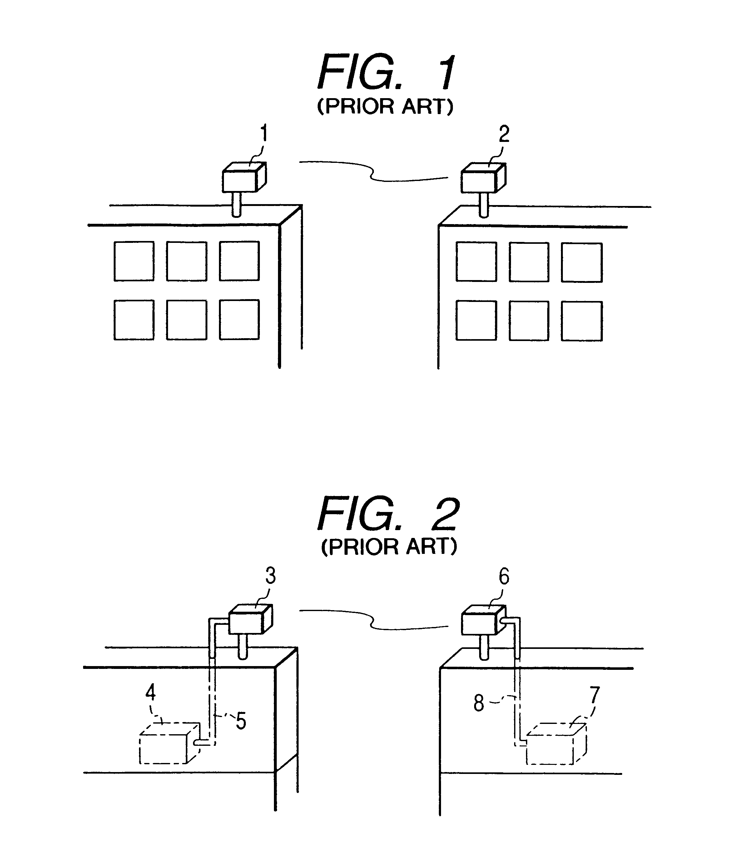
When the apparatus 1 or 2 must be installed in a place which makes it difficult to access depending on the situation, it is very difficult to confirm the operating state of the apparatus 1 or 2.

Method used


Image

  • Optical space communication apparatus
  • Optical space communication apparatus
  • Optical space communication apparatus

Examples


Embodiment Construction

The present invention will be described in detail with reference to the embodiments illustrated in FIGS. 3 to 8.

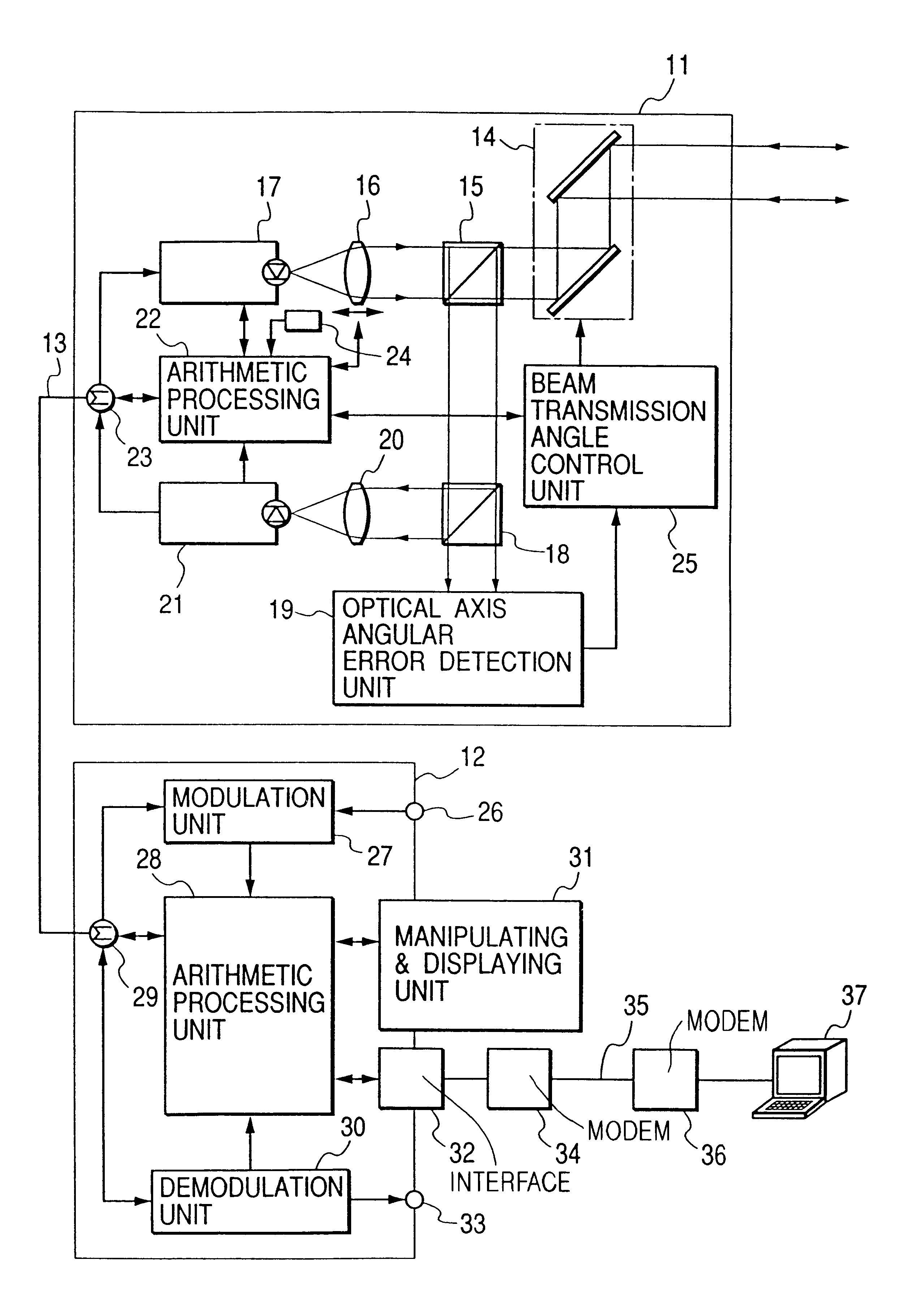
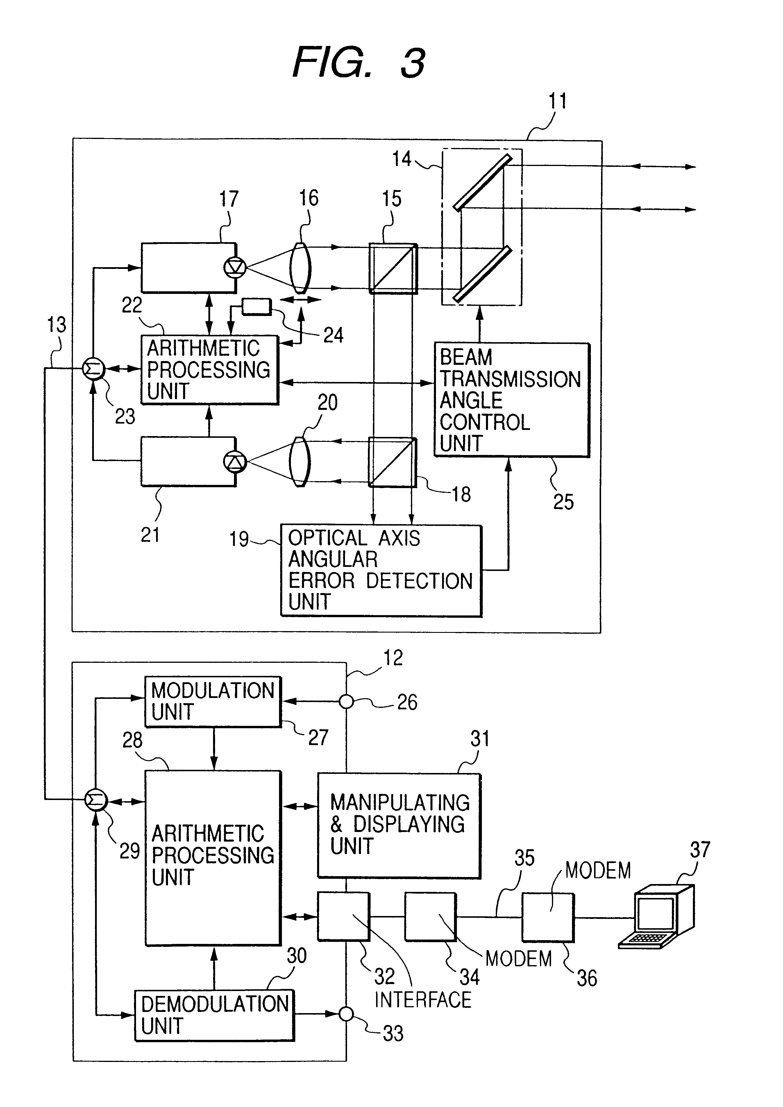
FIG. 3 shows the arrangement of an optical space communication apparatus according to an embodiment. This optical space communication apparatus comprises a main body head unit 11, a manipulating control unit 12, and a predetermined cable 13 which connects the units 11 and 12. An apparatus having the same arrangement as described above is located at a predetermined distance from the above apparatus to oppose it so as to perform optical radio information communication.

A beam transmission angle change means 14 is disposed at a position where a light beam is transmitted to or received from the opposing apparatus. A polarization beam splitter 15, an optical system 16, and an electro-optical conversion unit 17 are sequentially arranged in the reflection direction of the beam transmission angle change means 14. A beam splitter 18 and an optical axis angular error detection unit 1...


PUM


Abstract

In an optical space communication system, a remote controller is provided at an arbitrary position remote from an optical space communication apparatus. The optical space communication apparatus is provided with an interface device for exchanging status information of the operating apparatus, operation start setup / manipulation information or operating setup / manipulation information of the apparatus with the interface device. Communication between the remote controller and the interface device is made for a transmission light power, a transmission signal power, a reception light power, a reception signal power, a light beam transmission angle, a temperature of a predetermined portion in the apparatus, an angular error between the reception light and an optical axis of a light reception unit in the apparatus, a transmission light beam divergence angle or the like.

Description

BACKGROUND OF THE INVENTION1. Field of the InventionThe present invention relates to an optical space communication apparatus for performing optical radio information communication using a remote control means.2. Related Background ArtA conventional optical space communication apparatus for performing optical radio information communication is generally installed on the rooftop of a building or the like so as to clear any obstructing objects from the space between itself and an opposing apparatus separated by a predetermined distance. As shown in FIG. 1, optical space communication apparatuses 1 and 2 are installed on the rooftops of buildings to face each other. For example, a displaying unit for displaying operating states such as optical reception power, a setup unit for setup the divergence angle of a transmission light beam, and the like, a manipulating unit for adjusting the transmission angle of the light beam, and the like are arranged on the rear surface of each of the appa...

Claims


Application Information

Patent Timeline
IPC IPC(8): H04B10/10G06F3/00H04B10/00H04B10/07H04B10/077H04B10/079H04B10/11H04B10/114
CPCH04B10/1125
Inventor DEGURA, YASUSABURO
Owner CANON KK
Learn More