Robotic vehicle that tracks the path of a lead vehicle

a robot vehicle and lead vehicle technology, applied in the field of robot vehicles, can solve the problems of lack of maneuverability, difficulty in comparing with other freight haulers, and inability to maneuver,

Inactive Publication Date: 2002-12-17
MASTERS NATHAN EUGENE +2
View PDF5 Cites 127 Cited by
  • Summary
  • Abstract
  • Description
  • Claims
  • Application Information

AI Technical Summary

Problems solved by technology

Over-the-road transport companies find it difficult at times to compete with other freight haulers due to labor costs.
These long combination vehicles face the two interconnected problems of instability and lack of maneuverability, with each following dolly (with trailer attached) becoming less stable at speed and, also, each following dolly "cutting the corner" more than the vehicle segment in front of it during cornering.
The dolly tires however, do not steer relative to the dolly frame.
Commercial vehicles of either truck and full trailer or multi-trailer configurations which employ the standard Type A dollies generally possess undesirable characteristics such as limited maneuverability and instabilities caused by rearward amplification.
Rearward amplification is known to be the basic cause of many accidents in which roll over of the last trailer or second trailer occurs while the remaining elements of the vehicle remain unscathed.
However, they cause other problems such as introducing other types of instabilities, causing stresses on the rear of the forward trailer, and increasing unloading delays due to difficulty in accessing the back of the forward trailer for some configurations.
Steerable Type A dollies address the stability problems, but are even less maneuverable than Standard Type A dollies.
Although an improvement, these modes of steering for the long dollies, stability and cornering, did not truly track the path of the tractor, but only traced a path that represented a typical expected path for a given maneuver.
A similar problem exists in narrow city streets where equipment must be delivered to an emergency site such as a fire, or where the delivery of other materials is required.

Method used


Image

  • Robotic vehicle that tracks the path of a lead vehicle
  • Robotic vehicle that tracks the path of a lead vehicle
  • Robotic vehicle that tracks the path of a lead vehicle

Examples


first embodiment

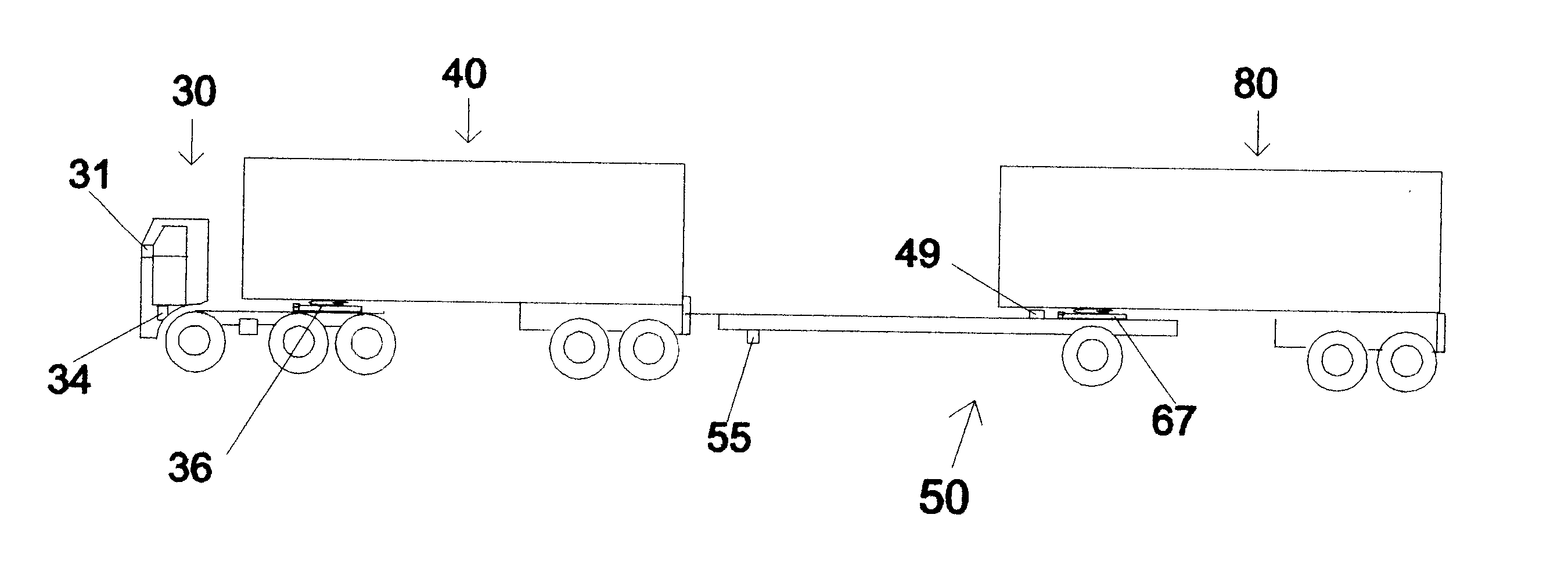
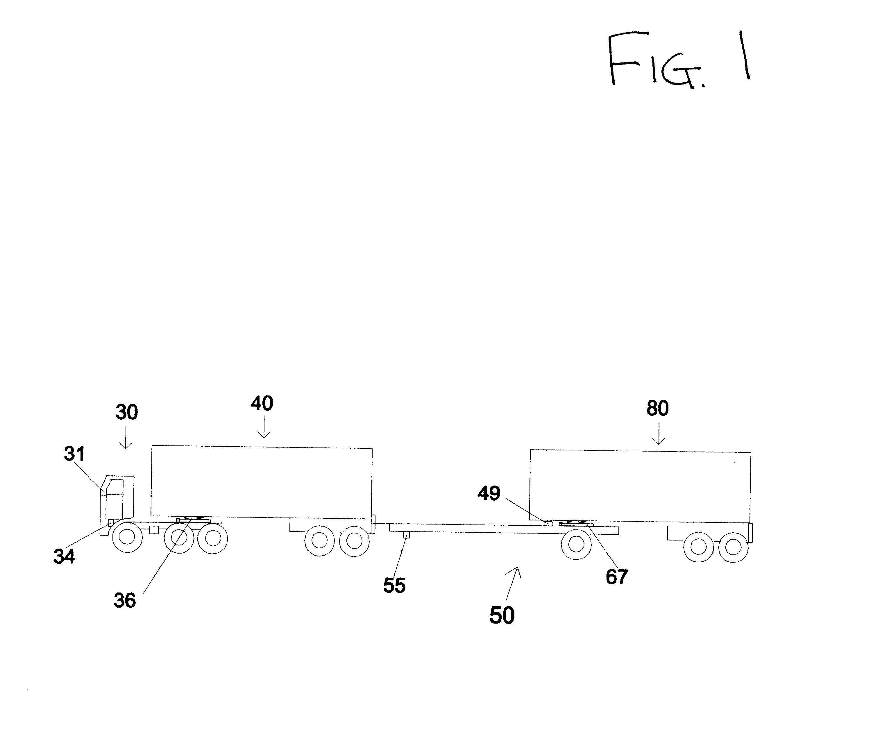
the invention has a long rigid main robotic tractor frame or tongue 55, which is the central rigid structural member. The front of the tongue 55 is attached at hitch latch 108 to the forward trailer 40.

At the rear of the robotic tractor there are three sections which each pivot in relation to each other, with a single vertical pivot point, best seen in FIG. 3. The uppermost section is a trailer mounting bar 66 with its two attached fifth wheels 67 L, R. The middle section is the robotic tractor frame or tongue 55. The lowest section is a steering axle assembly 60 with attached running wheels 70 L, R.

In the uppermost section, the trailer mounting bar 66 is free to swivel around the trailer mounting bar central pivot 65 (FIG. 3). This trailer mounting bar 66 pivots above the tongue 55 and around the same line as the steering axle assembly central pivot 58. Mounted on this trailer mounting bar 66 are the two fifth wheel latches 67 L, R by which the rear trailer 80 will be coupled to th...

second embodiment

PREFERRED SECOND EMBODIMENT OF INVENTION

FIGS. 8 and 9 show a robotic tractor with path tracking steering, variable ratio with oversteer steering, and traction kinking that is a preferred embodiment of the invention. This embodiment differs from the simpler robotic tractor with path tracking of the first embodiment in several ways. The robotic tractor length can be adjusted in this embodiment. The robotic tractor tongue is split into two parts, 55a and 55b, and 55b can be extended or retracted at the joint 144, with the pin and lock set 146 holding it in place. This embodiment also uses traction kinking to assist in turning corners. This embodiment uses two separate path tracking modes, relative angle path tracking mode and rate of orientation change path tracking mode, instead of only the relative angle path tracking mode used in the first embodiment of the invention. Also, the variable ratio with oversteer steering mode is included in the combination of steering modes to allow the ...

third embodiment

FIG. 14 shows a double-axle trailer or wagon that utilizes path tracking and variable ratio with oversteer mode steering with traction kinking. This wagon is designed to be pulled in a "Multiple Wagon Train" configuration behind a three-quarter ton pickup or some such vehicle, so it will be accordingly sized down somewhat from the robotic tractor with path tracking steering, variable ratio with oversteer and traction kinking discussed as the complex embodiment above. As was true for the robotic tractor however, this wagon will require three hitch balls on the towing vehicle. The second wagon in the train will use as input the orientation information from the upper 140 and lower partial circular tracks 75 of the first wagon in the train. The steering system for this wagon is identical to that for the robotic tractor except that control and shifting by the driver and the controlling microprocessor or computer 49 will utilize 12 volt solenoids and / or 12 volt DC motors instead of the ai...


PUM


Abstract

A method and apparatus for controlling the steering of a trailing section of a multi-sectioned vehicle is described. The trailing section follows the path of the first section. Data is acquired by a controller from sensors on the various sections. The controller then processes this data, generating a configuration needed for the controller-steered wheels to follow a path approximately equivalent to the path taken by the first steered section. Power is then applied by some means to steer these controller-steered wheels, forcing them into the desired configuration. The complexity of the control system can be varied with different algorithms providing alternative steering patterns as desired. This system can be extended with more trailing sections without necessitating more than minor changes to the control algorithms.

Description

This invention relates generally to the steering of the various sections of mobile articulated machines, and particularly to the steering of a section that is steered as a robot by a non-human control system. The preferred embodiments of the invention demonstrate a way of applying the principles of the invention to over-the-road tractor-trailer combinations. A driver controls the steering of a lead tractor, which carries the first trailer.Over-the-road transport companies find it difficult at times to compete with other freight haulers due to labor costs. Labor costs could be decreased if each tractor-trailer rig could carry more weight, but weight limits have been placed on roads and bridges for structural reasons. Multi-trailer arrangements have been seen as a possible solution to this problem because they spread the load over a longer stretch of pavement and reduce the columnar loading on bridges. These arrangements generally involve long combination vehicles, a semi-trailer carr...

Claims


Application Information

Patent Timeline
Patent Type & Authority Patents(United States)
IPC IPC(8): B62D53/08B62D53/00B62D53/06B62D13/00B62D13/02
CPCB62D13/005B62D13/025B62D53/005B62D53/06B62D53/0871
Inventor MASTERS, NATHAN EUGENEMASTERS, ANDREW C.MASTERS, CONNIE RUBY
Owner MASTERS NATHAN EUGENE
Why Eureka
Try Eureka