Lamp socket locking insert in combination with a medium screw lamp base

a technology of lamp base and locking insert, which is applied in the direction of energy-saving lighting, coupling device connection, sustainable building, etc., can solve the problems of preventing the interchange of compact fluorescent lamps with inexpensive incandescent bulbs, and the bulb will not operate, and achieves the effect of less expensiv

Inactive Publication Date: 2002-12-17
TECHN CONSUMER PRODS
View PDF8 Cites 45 Cited by
  • Summary
  • Abstract
  • Description
  • Claims
  • Application Information

AI Technical Summary

Benefits of technology

It is a further object of the present invention to provide a novel lamp screw base, whose threaded metal screw portion extends axially approximately one-half inch below the bottom of a ballast housing to prevent the housing from bottoming out against the inner surface of a reflector, when used.
It is still a further object of the present invention to provide a novel lamp-socket insert that coacts with the lamp screw base to prevent the interchangement, substitution or replacement of a protected lamp, with a less expensive bulb.
It is still yet a further object of the present invention to provide a novel lamp-socket insert having three tangential cantilever springlike vanes or tines, equally spaced 120 degrees apart, that are shaped to permit easy insertion upon clockwise rotation.
An additional object of the present invention is to provide a novel lamp socket insert, having spring-loaded tangential vanes or tines that become further engaged with, and bite into, the interior socket sidewall, so that a counterclockwise rotation prevents its removal.
A final object of the present invention is to provide a novel elongated lamp screw base and lamp-socket combination that prevents a standard incandescent lamp from being energized.

Problems solved by technology

If, however, the compact fluorescent lamp is substituted with a standard inexpensive incandescent bulb, the bulb will not operate, thereby preventing the interchangement of a compact fluorescent lamp with a standard inexpensive incandescent bulb.

Method used


Image

  • Lamp socket locking insert in combination with a medium screw lamp base
  • Lamp socket locking insert in combination with a medium screw lamp base
  • Lamp socket locking insert in combination with a medium screw lamp base

Examples


Embodiment Construction

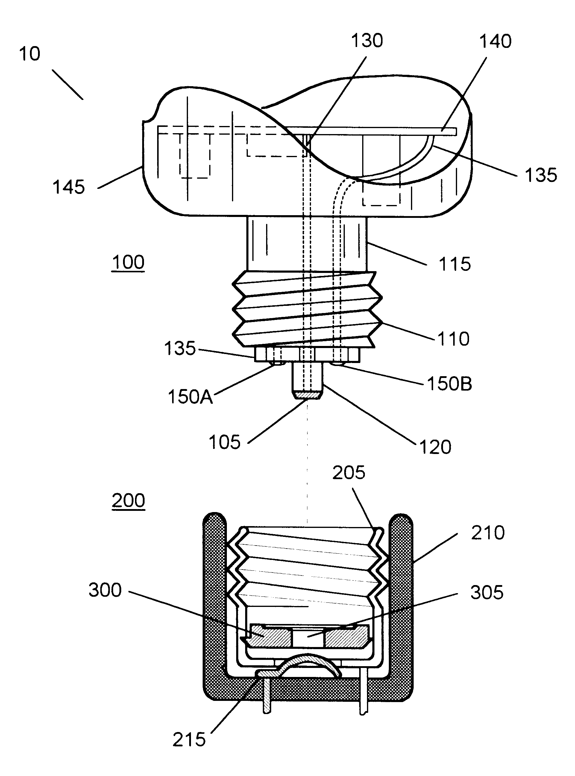
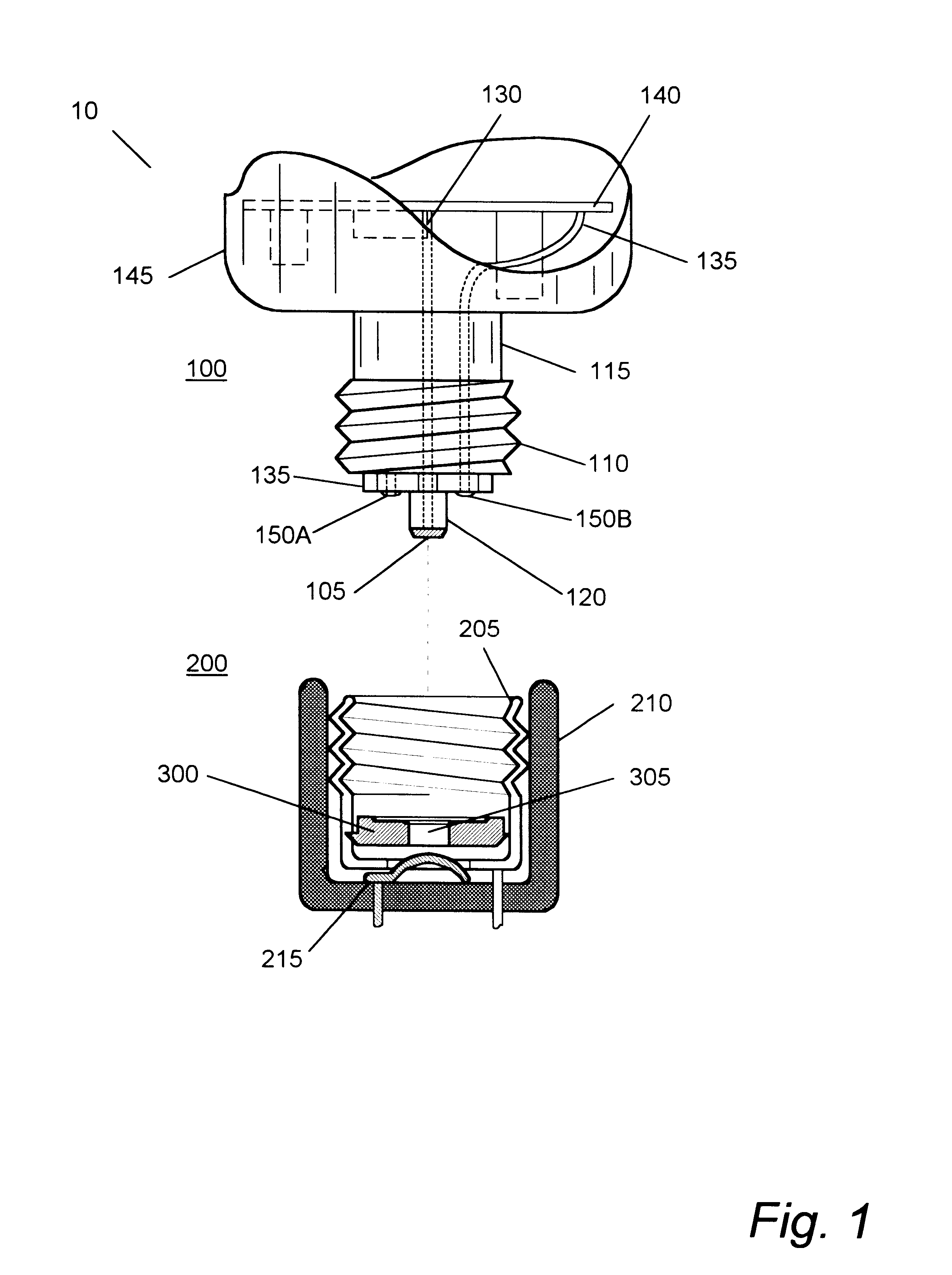
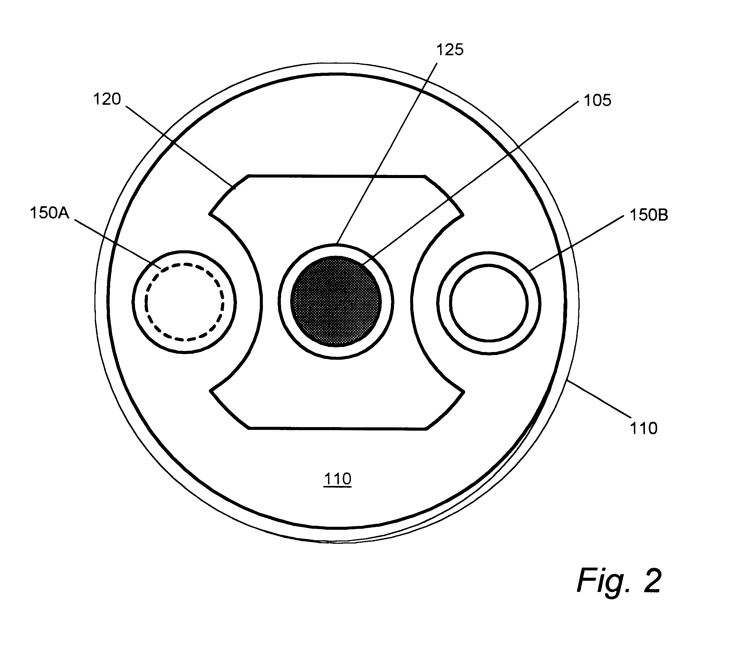
The present invention relates primarily to a combination base and lamp-socket insert assembly that when used, prevents the interchangement of an expensive compact fluorescent bulb with an inexpensive incandescent bulb.

For example, when the lamp is used in a hotel or motel setting, should the compact lamp be removed from the premises of its intended use, the conspicuous absence of the lamp is easily detected when the power switch is turned on. Further, should the compact lamp be removed from the premises and replaced with an incandescent bulb, the substitution may not be as easily detected. However, when the novel insert is used in a conventional lamp-socket, replacement with a standard incandescent bulb will not allow the bulb to function.

In the case of the theft of a fluorescent lamp, there is not only the loss of a compact lamp, but if the substitution of an incandescent bulb remains undetected, there is an increased operating cost because of the increased amount of electricity us...


PUM


Abstract

An apparatus that prevents the interchange or replacement of an expensive compact fluorescent lamp with a standard inexpensive incandescent bulb to diminish thefts of the more expensive lamp, by using a locking lamp socket insert in combination with newly designed screw lamp base that permits the operation of the compact fluorescent lamp. Should the compact fluorescent lamp be substituted with a standard inexpensive incandescent bulb, the center contact in the base of the incandescent bulb cannot touch the centrally located leaf-spring contact of the lamp socket, thereby preventing the incandescent bulb from operating. The lamp socket insert is a rigid plastic material such as nylon, shaped as a flat disk with three tangential cantilever, spaced apart vanes. A pointed end of each tine permits the insert to rotate upon insertion, but a counterclockwise rotation causes the tines to bite into the interior socket sidewalls preventing its counter-rotation and removal.

Description

The present invention relates primarily to a screw lamp base and locking lamp-socket device, in combination, and more particularly, to a screw lamp base, in combination with a locking lamp-socket insert that prevents the interchangement of a compact fluorescent lamp with an incandescent bulb when used in a conventional lamp socket.The demand for increased energy conservation has stimulated the development of compact electric discharge lamps, such a fluorescent lamps, as screw-in replacements for the standard incandescent bulb. As a result, the use of the compact fluorescent lamp has resulted in a substantial savings at a reduced operating and maintenance cost.While it is quite cost effective to replace an incandescent bulb with a compact fluorescent lamp, the converse, such as replacing a compact fluorescent lamp with an incandescent bulb, is no longer desirable.Recreational industries, such as hotels and motels, using these compact fluorescent lamps are subject to pilfering where t...

Claims


Application Information

Patent Timeline
Patent Type & Authority Patents(United States)
IPC IPC(8): H01R33/00H01R33/97H01R13/639H01R33/22H01R33/05
CPCH01R13/6397H01R33/22H01R33/971Y02B20/19Y02B20/00
Inventor YAN, ELLIS
Owner TECHN CONSUMER PRODS
Why Eureka
Try Eureka