

Spark plug
Inactive Publication Date: 2002-12-17
PYROTEK E3 LLC
View PDF193 Cites 107 Cited by
- Summary
- Abstract
- Description
- Claims
- Application Information
AI Technical Summary
Benefits of technology
It is a further object of the present invention to provide an improved spark plug which exhibits improved fuel efficiency.
It is a further object of the present invention to provide an improved spark plug which exhibits improved combustion pressure.
It is a further object of the present invention to provide an improved spark lug which provides decreased pollution.
Problems solved by technology
It is believed that concentric ring designs, no matter how minimal the length of the concentrically curved section, perform no better in practice than conventional spark plug designs.
Method used
View moreImage
Smart ImageViewing Examples

Examples
second embodiment
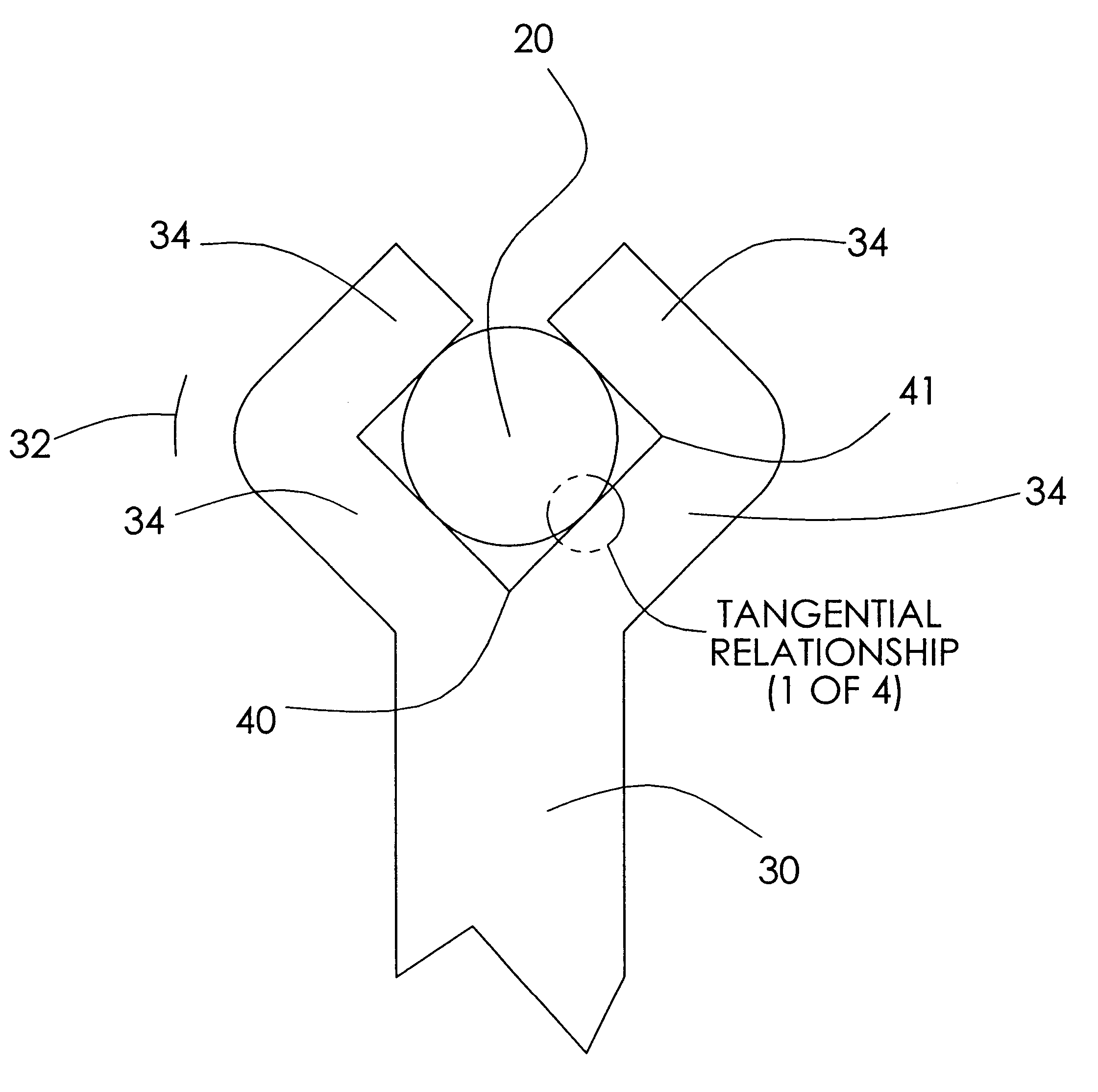
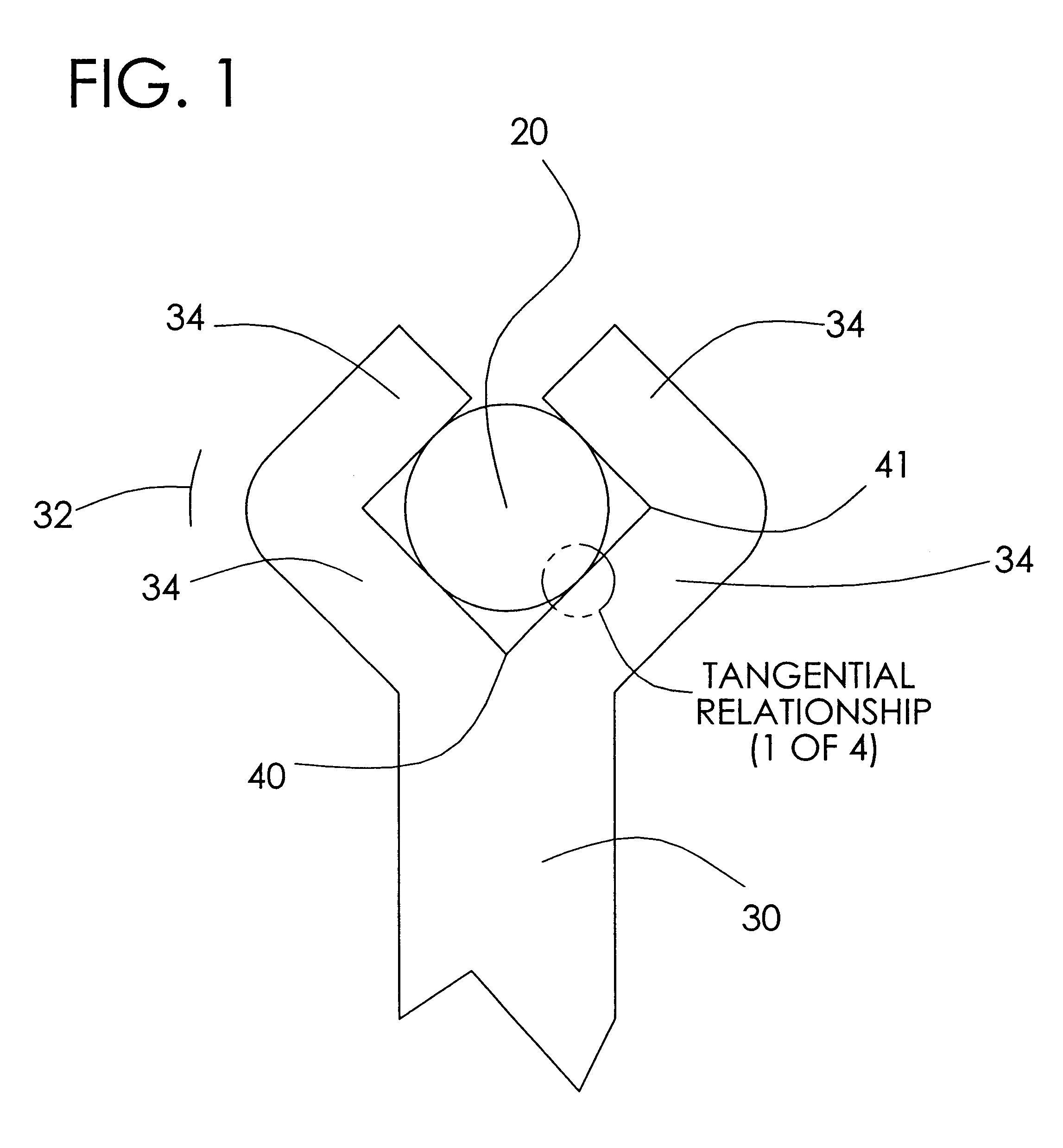
FIG. 3 is a top view of two electrodes, a ground electrode 51 and a center electrode 20, used in the present invention, which could be considered a "forked" configuration, with two tangential relationships and one vertex.
third embodiment
FIG. 4 is a top view of two electrodes, a ground electrode 52 and a center electrode 20, used in the present invention, which includes three segments and three tangential relationships and two vertexes (a.k.a "vertices").
fourth embodiment
FIG. 5 is a top view of two electrodes, a ground electrode 53 and a center electrode 20, used in the present invention, with six segments, up to five vertexes, and at least four tangential relationships.
Login to View More PUM
 Abstract
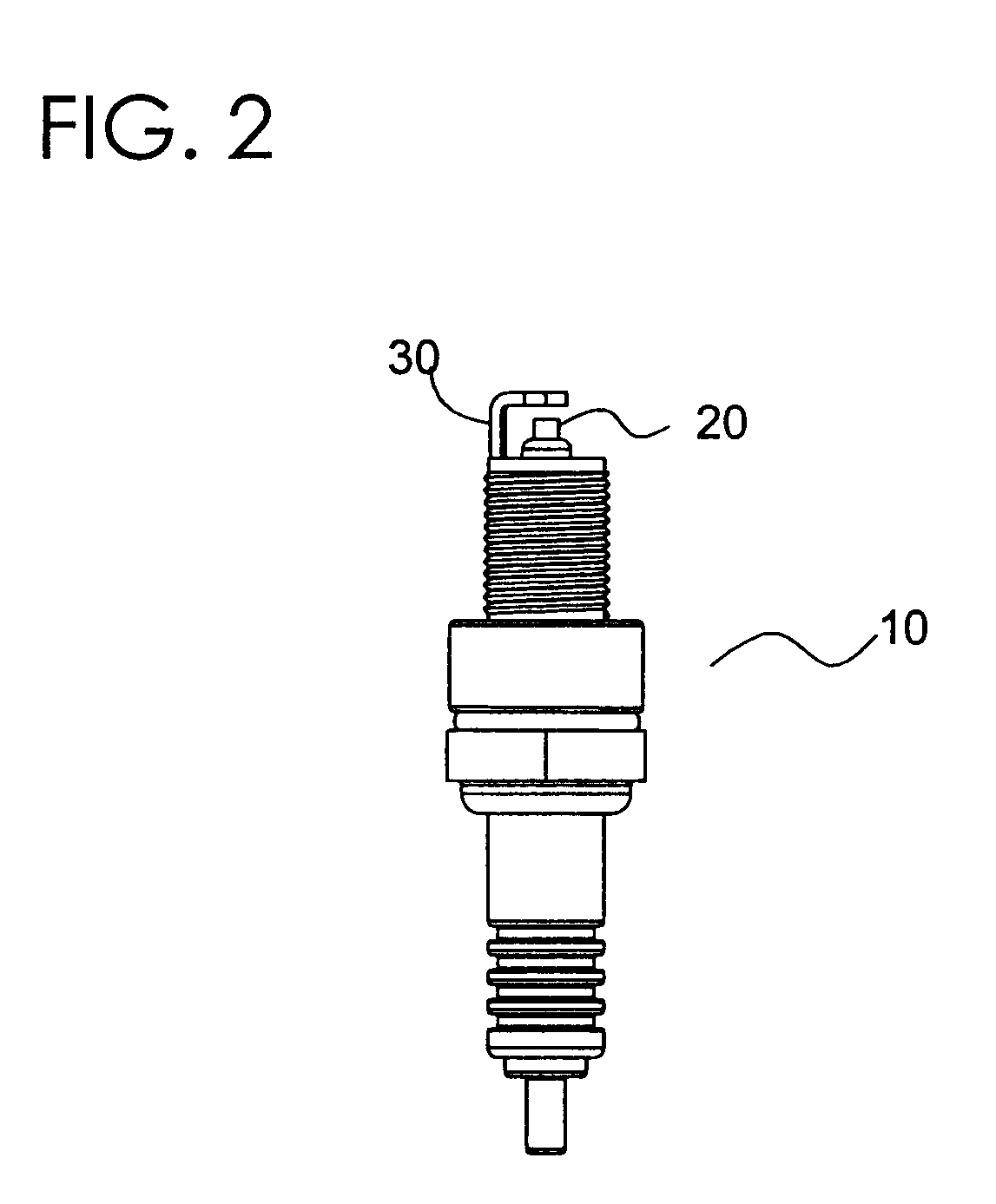
The present invention relates to improved spark plugs for igniting a fuel charge in an internal combustion engine, and is particularly concerned with an improved spark plug construction which improves combustion pressure and fuel mileage and diminishes exhaust pollution. The spark plug includes a center electrode and a ground electrode. In one embodiment, the ground electrode has an elongate edge that extends past the major dimension of the center electrode. The elongate edge can either be positioned substantially tangentially to or within a "zone" outside of the center electrode's periphery. Preferably, the edge of the center electrode and the lower interior edge of the ground electrode will be presented towards one another such that the edges are or are among the closest portions within the sparking region.
Description
The present invention generally relates to spark plugs for igniting the fuel charge in an internal combustion engine, and is particularly concerned with an improved spark plug construction which improves combustion pressure, fuel mileage and diminishes exhaust pollution as compared with known prior art plugs.Prior art spark plugs are well known. Such spark plugs typically include a center electrode and a ground electrode spaced apart from the center electrode. When a sufficient electrical potential is provided across the gap, a spark jumps across the gap. This spark can be used to ignite an air-fuel mixture within an internal combustion engine.U.S. Pat. No. 5,051,651 ("the '651 patent") details a "cylindrical hole" that is created around the center electrode by shielding of the outer ground electrode. The '651 patent asserts that "ignition seeds" multiply inside of this cylindrical hole. The ground electrode, in all examples, has a "substantially concave inner surface complimenting ...
Claims
Login to View More Application Information
Patent Timeline
 IPC IPC(8): H01T13/20H01T13/32
CPCH01T13/32
InventorGARRETT, III, NORMAN H.
OwnerPYROTEK E3 LLC