Roof construction for a motor vehicle having a removable roof

a technology for motor vehicles and roofs, which is applied in the direction of roofs, windscreens, windows, etc., can solve the problems of occupying a considerable amount of storage space, unable to provide a loading area, and extremely bulky packaging

Inactive Publication Date: 2002-12-24
EDSCHA LKW SCHIEBEVERDECKE +1
View PDF13 Cites 31 Cited by
  • Summary
  • Abstract
  • Description
  • Claims
  • Application Information

AI Technical Summary

Benefits of technology

With the roof removed, the roof construction according to the present invention enables stacking of the first and second roof parts, in which the curved profile of the two roof parts runs essentially in the same direction and therefore the additional storage space required because of the curvature or transverse bending in the curved profile of the two roof parts has only to be made available once on account of the stackability. It is thereby advantageously possible to move the first, front hard roof part rearward, as seen in the direction of travel, in a relatively flat manner and similarly to allow the rear, second roof part to slide flat into the trunk of a motor vehicle. For this purpose, the trunk can expediently be opened rearward via a pivoting joint arranged in the region of its lock provided at the rearward end.
Since the second roof part, which essentially comprises the rear window, is lowered synchronously with the moving of the first roof part, the first roof part can be pulled down rearward from the cowl in a predominantly horizontal movement without colliding with the second roof part, and thus makes possible a simple locking arrangement to the cowl.
It is furthermore possible to realize the comparatively simple sequence of movements with a low outlay by the fact that one drive per side drives both roof parts. By this means, it is possible, in particular, to synchronize the two roof parts mechanically without separate sensor arrangements for detecting the position of the two parts, with the result that the sequence of movement is always coordinated and also, in the event of being actuated manually in emergency mode, is coupled in such a manner that the two roof parts do not impede each other. At the same time, the coupling secures the mutual locking arrangement of the two articulated connections.
A seven-bar linkage is preferably provided in each case for the drive of the first roof part and a four-bar linkage for the drive of the second roof part. The seven-bar linkage is a four-bar linkage in which the articulation on the vehicle body of one of the two links can be changed via a control link which is articulated on the vehicle body, the change, because of a change in position of the other link, being transmitted via a coupling rod. The other three articulations are therefore the two articulations of the coupling link on the two links and the articulation of the control link on a main bearing on the vehicle body. The configuration of a seven-bar linkage makes it advantageously possible to provide a rapid sequence of movement without high acceleration values being reached for this--unlike in the case of a four-bar linkage.
The two links of the seven-bar linkage are preferably connected to each other via a coupling rod and a control link, which is mounted on the main bearing which is fixed on the vehicle, in such a manner that the coupling rod drives the control link about its articulation on the main bearing, the control link bearing, likewise eccentrically with respect to its mounting, the articulation of the other link of the seven-bar linkage and therefore first of all pulling said link and causing a tilting movement which hardly raises the front edge of the first roof part enabling the latter to be brought in a simple manner out of interference with the boundaries in the region of the passenger cell roof. It is therefore also possible for the first roof part to travel around a roll bar of the motor vehicle. The first roof part is not pivoted out to a very high extent and so a small amount of opening can be provided for the rear lid. The four-bar linkage displaces the rear window and the second roof part synchronously into the trunk. The first roof part is lowered relatively far forward into the vehicle body and rotated into an end position, as a result of which the aperture of the rear lid can be of correspondingly smaller dimensions, and further a uniform speed without relatively great changes can be set.
When the roof has been retracted, the C-struts in the trunk protrude into a region between the rear light and wheel housing, while the horizontal region of the roof part is arranged entirely in the vicinity of the trunk lid. The second roof part is arranged below the flat part very close below the first roof part. By this means, in the region between the two C-struts in the trunk, a loading space is produced which allows a deep loading option extending to below the second roof part. This storage space is advantageously also available during the lowering and re-erection of the hard roof, which means that this region does not have to be unloaded before the roof is pivoted.

Problems solved by technology

Such packing is extremely bulky and takes up a considerable amount of storage space.
Moreover, the front roof part is not suitable as a covering for the storage space and so a separate covering has to be provided.
Finally, because the front roof part is removed flat, the roof construction requires a retractable roll bar, since a static roll bar would impede the lowering of the roof.
Furthermore, provision is not made for a loading area to remain below the rear roof part lowered into the trunk.

Method used


Image

  • Roof construction for a motor vehicle having a removable roof
  • Roof construction for a motor vehicle having a removable roof
  • Roof construction for a motor vehicle having a removable roof

Examples


Embodiment Construction

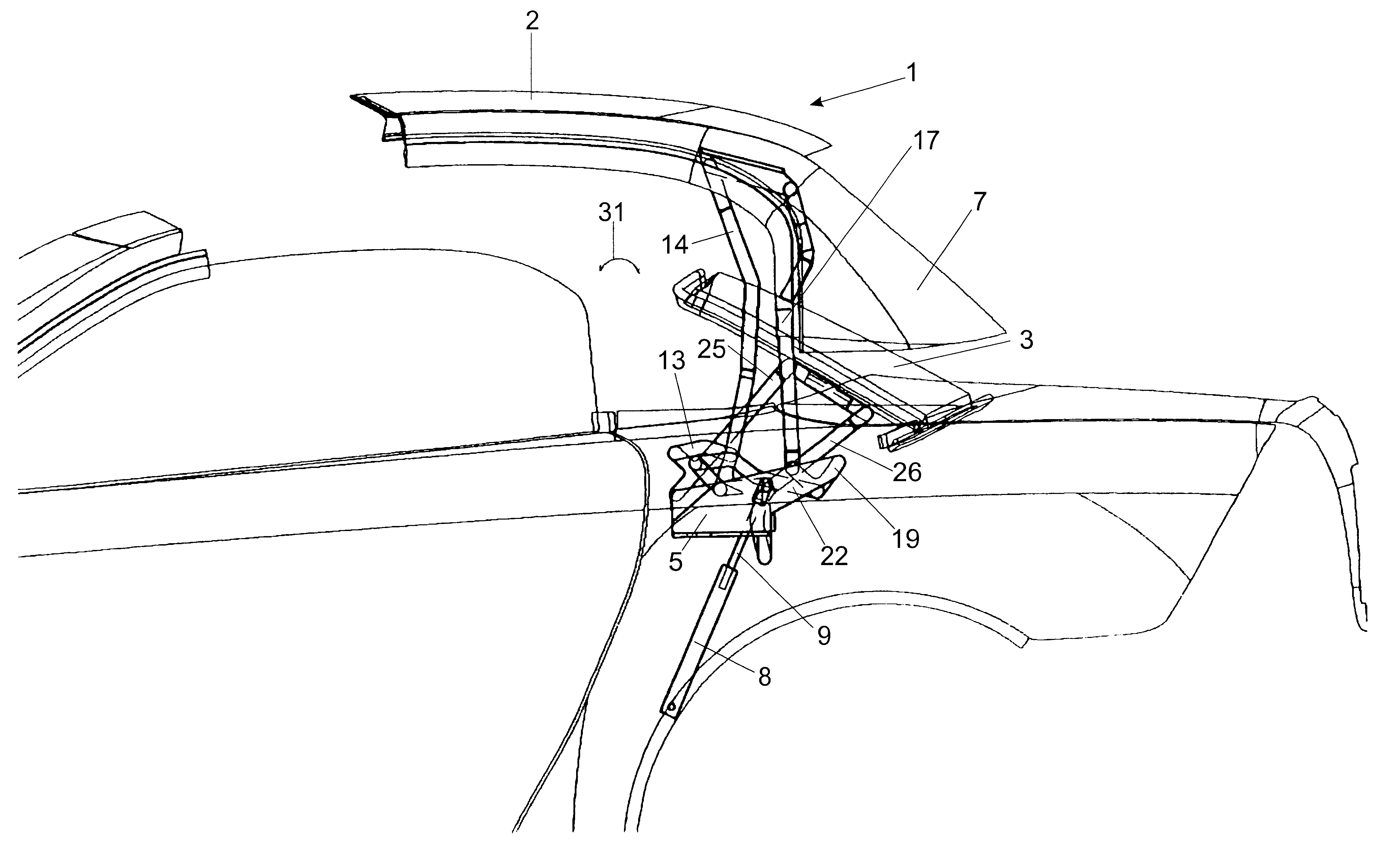
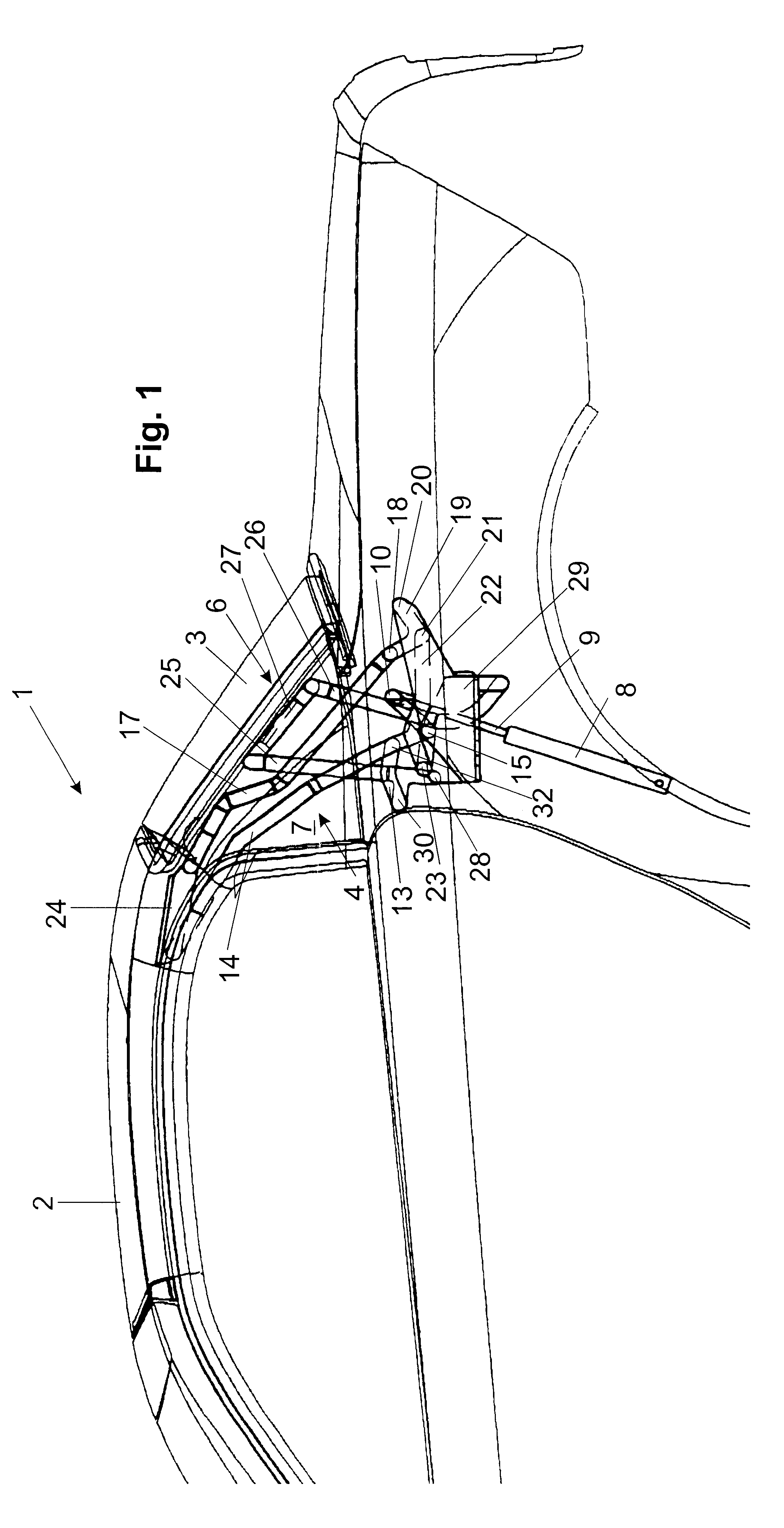
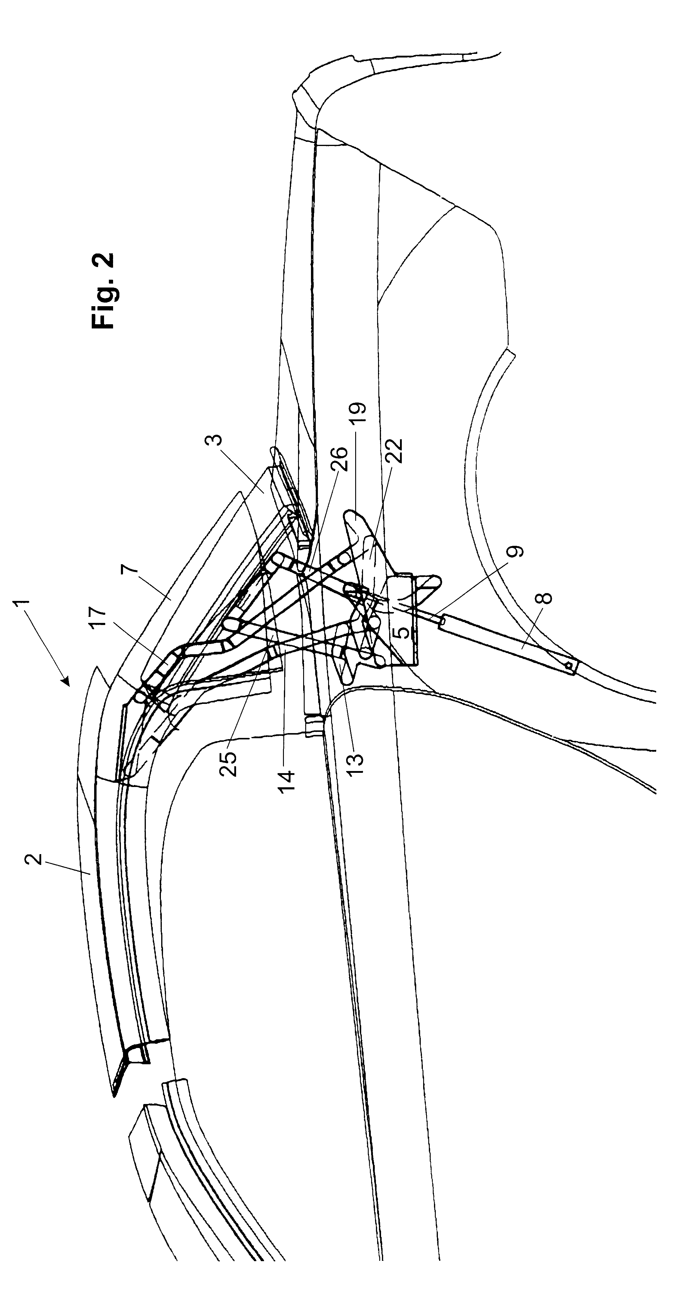
FIGS. 1 to 7 show part of a motor vehicle, which is denoted as a whole by the reference number 1, with a removable roof which is designed as a hard shell roof or a hard top and comprises a first, front roof part 2 and a second, rear roof part 3.

The front roof part 2 is connected via a first, articulated connection, which is designed as a seven-bar linkage 4, to a main bearing 5 which is fixed on the vehicle body. The rear roof part 3 is connected by means of a four-bar linkage 6 as an articulated connection to the main bearing 5 which is fixed on the vehicle body. The first roof part furthermore has C-struts 7 adjoined to it which essentially laterally enclose the second roof part 3. The second roof part in the present case is a framed rear window.

The drive of the kinematic arrangement defined by the seven-bar linkage 4 and the four-bar linkage 6 takes place via a hydraulic piston-cylinder unit 8 whose piston rod 9 engages on a projection 10 of a first link 14 of the seven-bar linka...


PUM


Abstract

A roof construction for a motor vehicle having a removable roof, includes a first, front hard roof part, a main bearing fixed on the motor vehicle body, a first, articulated connection, the first, front hard roof part being connected via the first, articulated connection to the main bearing, the first, front hard roof part being pivotable from a closed position into a lowered position in a trunk by means of the first, articulated connection, a second roof part containing a rear window, a second, articulated connection, the second, articulated connection being arranged pivotably outside the first, articulated connection on the same main bearing, the second roof part being pivotable from a closed position into a lowered position in the trunk via the second, articulated connection, the first, front hard roof part being arranged in its lowered position above the second roof part, and a loading area for loading purposes remaining below the second roof part.

Description

The invention relates to a roof construction for a motor vehicle having a removable roof, comprising a first, front hard roof part; a main bearing fixed on the motor vehicle body; a first, articulated connection; said first, front hard roof part being connected via said first, articulated connection to said main bearing; said first, front hard roof part being pivotable from a closed position into a lowered position in a trunk by means of said first, articulated connection; a second roof part containing a rear window; a second, articulated connection; said second roof part being pivotable from a closed position into a lowered position in the trunk via said second, articulated connection; said first, front hard roof part being arranged in its lowered position above said second roof part.DESCRIPTION OF THE PRIOR ARTGerman Patent No. DE 196 35 536 C1 describes a roof construction in which an open passenger car is designed with a two-part, collapsible fixed roof in which a rear roof part...

Claims


Application Information

Patent Timeline
Patent Type & Authority Patents(United States)
IPC IPC(8): B60J7/14B60J7/08B60J7/00B60J7/16
CPCB60J1/1823B60J7/146
Inventor OBENDIEK, KLAUS
Owner EDSCHA LKW SCHIEBEVERDECKE
Why Eureka
Try Eureka