Electronic flat key

a technology of electronic flat keys and flat keys, applied in the field of electronic flat keys, can solve the problems of battery compartment falling out, electrical shadowing of transmitting or receiving elements located in the grip element casing,

Inactive Publication Date: 2002-12-31
VALEO & SCHLIESSYST
View PDF11 Cites 33 Cited by
  • Summary
  • Abstract
  • Description
  • Claims
  • Application Information

AI Technical Summary

Problems solved by technology

The drawbacks of these known flat keys include the fact that the side elements cannot be made of metal, for a corresponding grip element casing would mean that the transmitting or receiving elements located in the grip element casing would be electrically shadowed

Method used


Image

  • Electronic flat key
  • Electronic flat key

Examples


Embodiment Construction

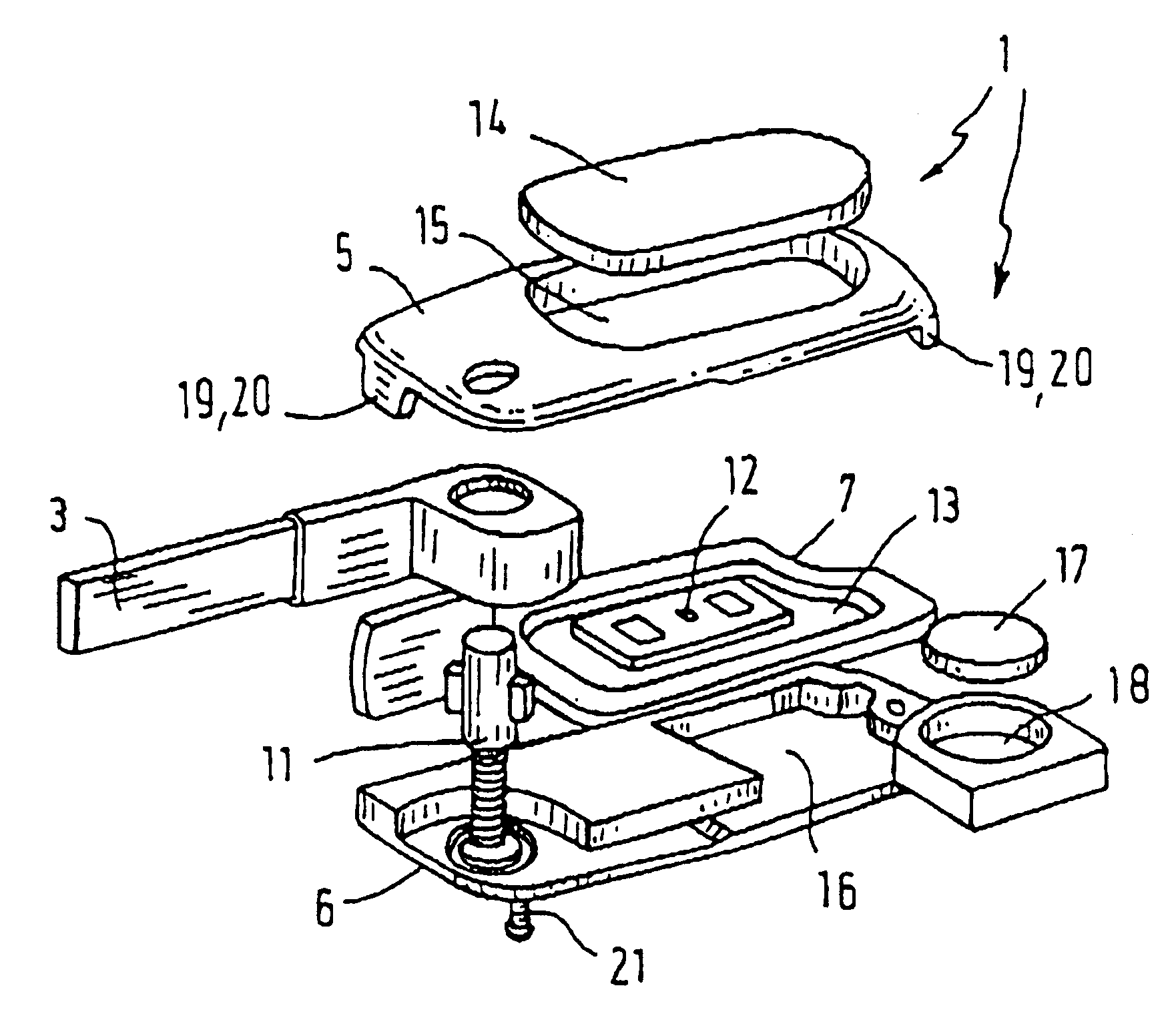
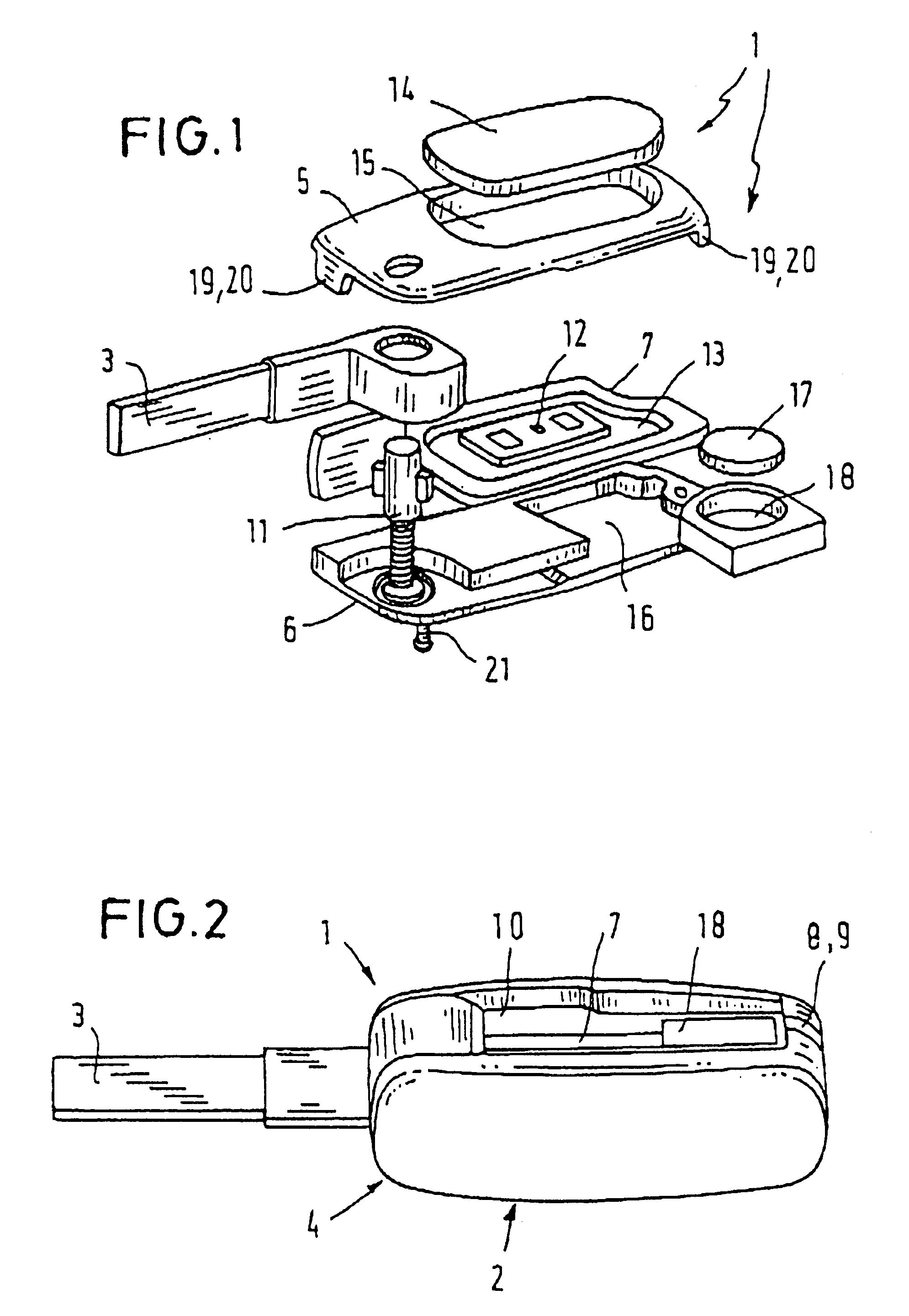
In FIGS. 1 and 2, 1 designates an electronic flat key consisting essentially of a grip element 2 and a key bit 3. The grip element 2 includes a casing 4 with two shell-type side elements 5, 6 made of a light metal (e.g. aluminum) which are adapted to be clipped together. Between the side elements 5, 6 is a central element 7 made of plastic in the shape of a frame, which extends in sub-portions 8 of the grip element casing 4 as far as the outer surface 9 of the casing.

The key bit 3 is rotatably mounted in the grip element casing 4 and can be swiveled from a retracted position into an extended position. In the retracted position it is located in a lateral wall 10 in the grip element casing 4 and is held in this position by locking means. A rotary spring swivels the key bit 3 into its extended position by applying pressure to a spring-actuated push-button 11.

The grip element casing 4 encloses an electronic switching device 12 (e.g. a transponder) for remote operation of a vehicle lock ...


PUM


Abstract

The invention relates to an electronic flat key having a grip element (2) and a key bit (3), the grip element (2) including a casing (4) in which are arranged an electronic switching device (12) for remote operation of a lock or locking system and a holder (16) for at least one battery (17) for supplying power to the switching device, the grip element casing (4) including two side elements (5, 6) constructed in the form of shells, and the key bit (3) being arranged on the grip element casing (4) in a manner enabling it to be swiveled from a retracted position, in which it is situated in a lateral well (10) in the grip element casing (4), into an extended position. In order for the grip element casing (4) to also consist of metallic side elements (5, 6) constructed in the form of shells, without this substantially affecting (electrically shadowing) the transmitting and/or receiving elements located in the casing (4) for remote operation or a lock or locking system, the invention proposes that between the two side elements (5,6) of the grip element casing (4), which are made of metal and are constructed in the form of shells, there is arranged a central element (7) of frame-like construction which is made of a material that does not conduct electricity, which extends peripherally at least in sub-portion (8) of the grip element casing (4) as far as the outer surface (9) of the casing (4) and is sufficient for conveying an adequate signal between the transmitting and/or receiving elements located in the grip element casing (4) and those located in the lock zone or locking system zone.

Description

The invention relates to an electronic flat key in accordance with the features of the preamble of Claim 1.DESCRIPTION OF THE PRIOR ARTFlat keys of this type are for example known from DE 39 02 537 C2. They are essentially composed of a grip element and a key bit, the grip element including a casing and the key bit being arranged on the casing of the grip element in a manner enabling it to be swiveled from a retracted position, in which it is located in a lateral well in the grip element casing, into an extended position. In the case of the conventional flat key the grip element casing consists of two shell-type plastics side elements joined together, which enclose an electronic switching device for remote operation of a lock or locking system. In addition, there is disposed in the grip element casing a holder which houses the batteries for supplying power to the electronic switching device. The holder is contiguous with the surface of one of the two shell-type side elements and is ...

Claims


Application Information

Patent Timeline
IPC IPC(8): A45C11/32A45C11/00E05B19/00E05B19/04G07C9/00E05B19/08
CPCA45C11/324E05B19/043G07C9/00944G07C2009/00587G07C2009/00952Y10T70/7808Y10T70/7825Y10T70/7876
Inventor HEUSSNER, UWE
Owner VALEO & SCHLIESSYST
Why Eureka
Try Eureka