Communication device having a spurious wave blocking circuit formed of a plural fundamental pattern

a technology of spurious wave and circuit, applied in waveguides, oscillators, electrical equipment, etc., can solve the problems of severe restrictions on the size of transmission lines and electrode removal

Inactive Publication Date: 2003-01-07
MURATA MFG CO LTD
View PDF8 Cites 7 Cited by
  • Summary
  • Abstract
  • Description
  • Claims
  • Application Information

AI Technical Summary

Problems solved by technology

Therefore, there has arisen the problem that if an electromagnetic field is disturbed in input-output portions and bends of the transmission lines, a spurious mode wave such as a so-called parallel plate mode wave or the like is excited between the two parallel plane conductors, and the spurious mode wave is propagated between the plane conductors.
In some cases, problematically, interference is caused by the spurious mode leakage wave between the adjacent transmission lines, so that a signal leaks between the lines, and so forth.
Restrictions on the size of the transmission line become severe.
However, in this case, the new problem arises that the area where the electrode is removed acts as a kind of resonator.

Method used


Image

  • Communication device having a spurious wave blocking circuit formed of a plural fundamental pattern
  • Communication device having a spurious wave blocking circuit formed of a plural fundamental pattern
  • Communication device having a spurious wave blocking circuit formed of a plural fundamental pattern

Examples


Embodiment Construction

Principle

The total reflection condition of a four-port circuit as an example of a circuit pattern for use in a spurious suppression mechanism is determined based on a characteristic value theory by using the periodicity of the circuit pattern and moreover, the condition that an input wave is totally reflected.

First, an arbitrary four-port circuit is simply expressed as in FIG. 5. Assuming that there is no loss in the circuit, the unitary condition is valid. The respective parameters of S.sub.11, S.sub.12, S.sub.13, S.sub.14, S.sub.21, S.sub.22, S.sub.23 . . . S.sub.42, S.sub.43, S.sub.44 can be reduced to the four parameters, that is, S.sub.11 to S.sub.41. The scattering matrix can be expressed as follows. ##EQU1##

The symmetric condition of the circuit is applied to this scattering matrix. In the case in which the circuit is symmetric about two axes A-A' and B-B', as shown in FIG. 5, the whole of the four-port circuit can be analyzed by analysis of the one-port circuits in which eve...


PUM


Abstract

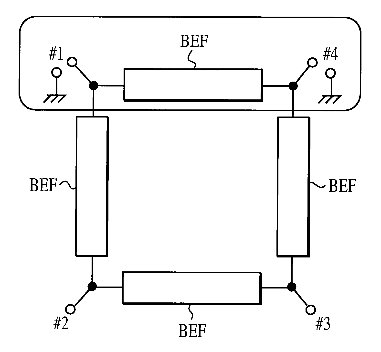
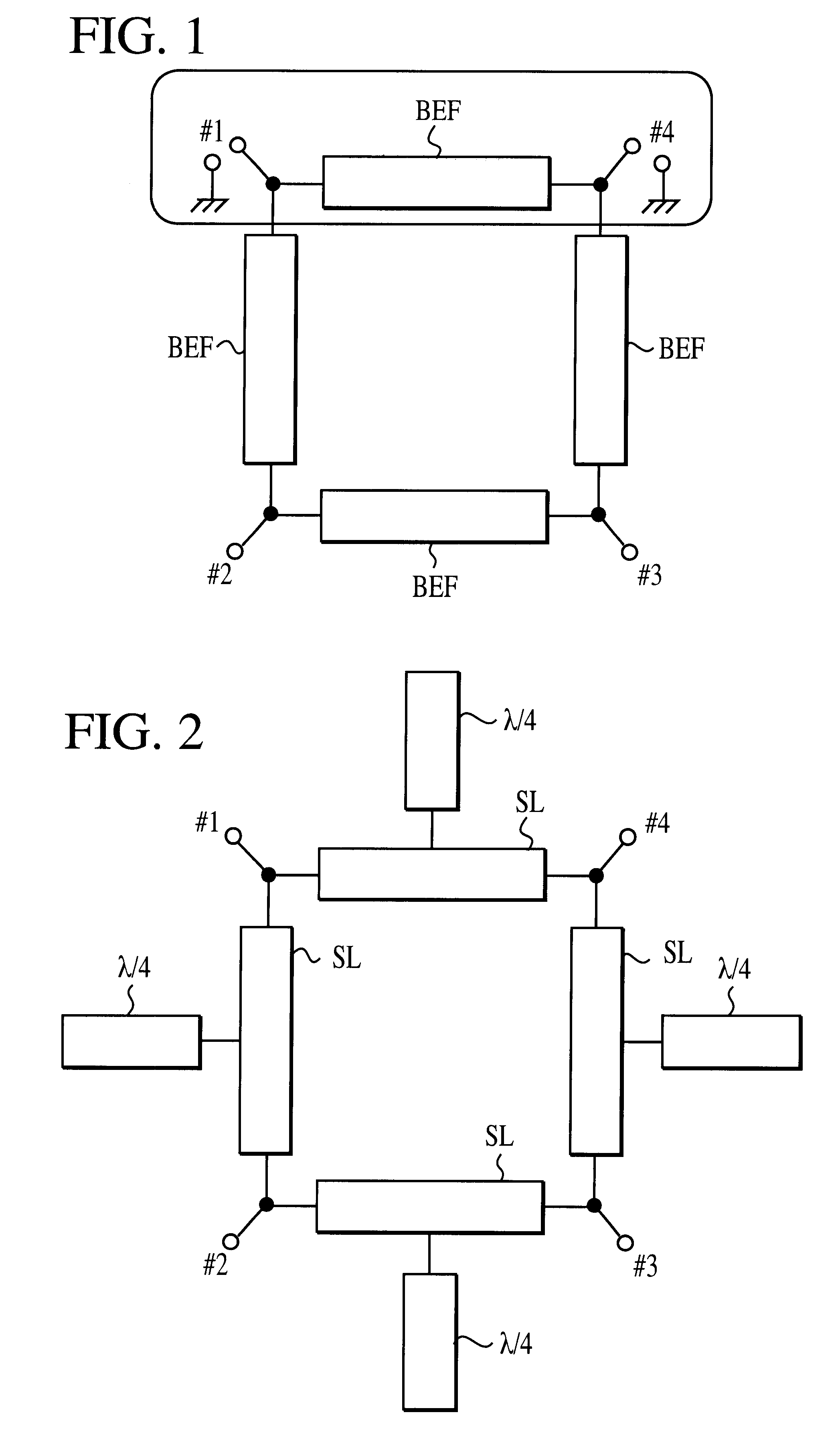
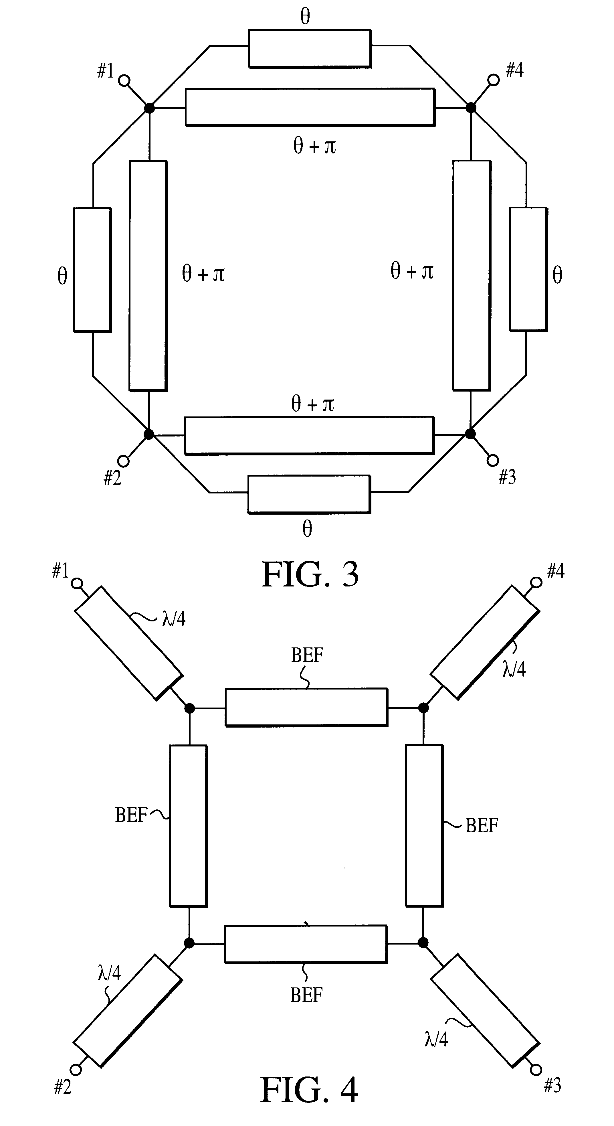
Electrodes are formed on the upper and under faces of a dielectric plate. For example, plural fundamental patterns having four ports and a quadrangular shape are arranged thereon. A strip conductor of a two-port circuit is determined so that adjacent two-port circuits of the respective fundamental patterns have a band-stop filter characteristic.

Description

1. Field of the InventionThe present invention relates to a high frequency circuit device such as a waveguide, a resonator, or the like including two parallel plane conductors, and a communication device using the high frequency circuit device.2. Description of the Related ArtAs transmission lines for use in a microwave or millimeter-wave band, different types of transmission lines are employed, such as grounded coplanar transmission lines each containing a dielectric plate having a ground electrode formed substantially on the whole of one face thereof and a coplanar line formed on the other face thereof, grounded slot transmission lines each containing a dielectric plate having a grounded electrode formed on one face thereof and a slot formed on the other face thereof, planar dielectric transmission lines each containing a dielectric plate having slots formed on both of the faces of the dielectric plate, in opposition to each other through the dielectric plate, and so forth.All of ...

Claims


Application Information

Patent Timeline
Patent Type & Authority Patents(United States)
IPC IPC(8): H01P3/00H01P1/16H01P1/212H01P3/02H01P3/08H01P3/16H03B5/18
CPCH01P3/00H01P1/16
Inventor IIO, KENICHIISHIKAWA, YOHEI
Owner MURATA MFG CO LTD
Why Eureka
Try Eureka