Image forming apparatus having paper dust removing means

a technology of paper dust removal and image forming apparatus, which is applied in the direction of electrographic process apparatus, instruments, optics, etc., can solve the problems of defective visible image, paper dust can degrade the resultant visible image, and devices are unable to remove filler material in sufficient quantities

Inactive Publication Date: 2003-01-07
BROTHER KOGYO KK
View PDF21 Cites 18 Cited by
  • Summary
  • Abstract
  • Description
  • Claims
  • Application Information

AI Technical Summary

Problems solved by technology

When the toner is reused during a later development process, the paper dust can degrade the resultant visible image.
The filler material can cause filming and so magnify the problem of the defective visible images.
However, these devices (1) through (3) have the following problems.
However, the brush in these devices is unable to sufficiently remove filler material such as talc in the paper dust from an acidic paper.
The collected talc will generate an undesirable fogging phenomenon during subsequent development processes.
That is, when an electrostatic latent image is developed with toner mixed with talc, fogging will be formed on the white areas of a developed image and as a result the image will be poor.
However, the non-woven fabric will scrape the paper dust across the surface of the photosensitive drum.
The performance of the photosensitive drum will deteriorate.

Method used


Image

  • Image forming apparatus having paper dust removing means
  • Image forming apparatus having paper dust removing means
  • Image forming apparatus having paper dust removing means

Examples


first embodiment

An image forming apparatus according to a first embodiment of the present invention will be described below with reference to FIGS. 1-7.

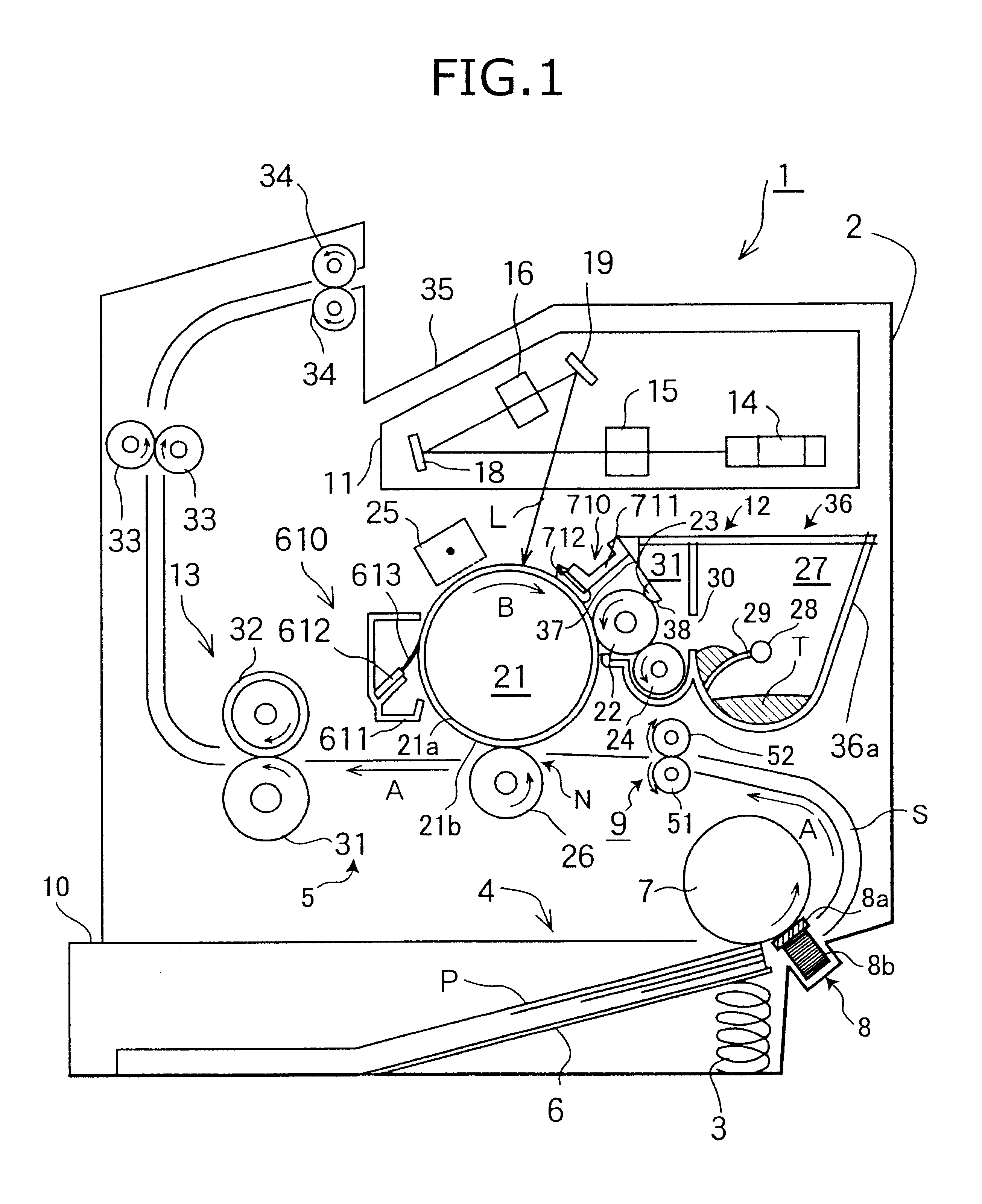
FIG. 1 is a cross-sectional view showing essential parts of a laser printer 1 that serves as the image forming apparatus according to the first embodiment. As shown in FIG. 1, the laser printer 1 includes a housing or casing 2, in which a sheet feeding unit 4 and an image printing unit 5 are mounted. The sheet feed unit 4 is for supplying sheets of paper P to the image printing unit 5. The sheets of paper P serve as recording media to be printed with visible toner images. The image printing unit 5 is for printing visible toner images onto the sheets of paper P.

As shown in FIG. 1, the sheet feeding unit 4 is disposed at a bottom portion of the housing 2. The sheet feeding unit 4 includes: a sheet supply tray 10, a sheet separation member 8, a sheet supply roller 7, and a register roller unit 9. The sheet supply tray 10 is mounted detachably to the ca...

second embodiment

A second embodiment will be described below with reference to FIGS. 8-13

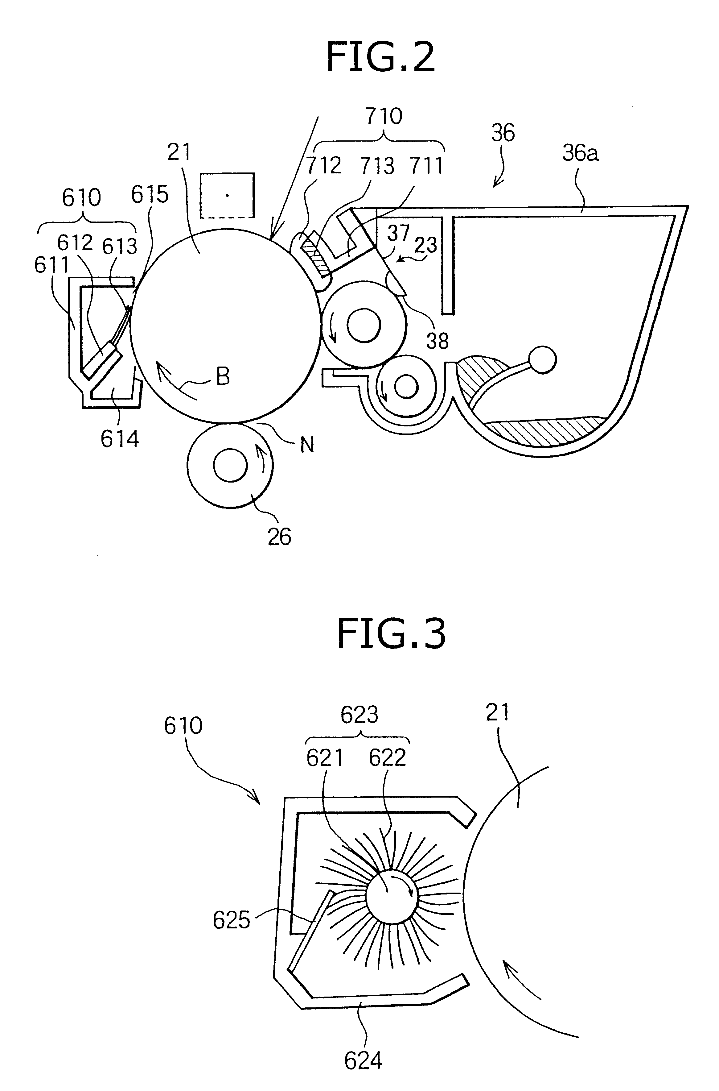
According to the first embodiment, the image forming unit 12 is fixedly mounted in the casing 2. In other words, the photosensitive drum 21 and the charge unit 25 are mounted directly to the casing 2. The development cartridge 36 is detachably mounted to the casing 2.

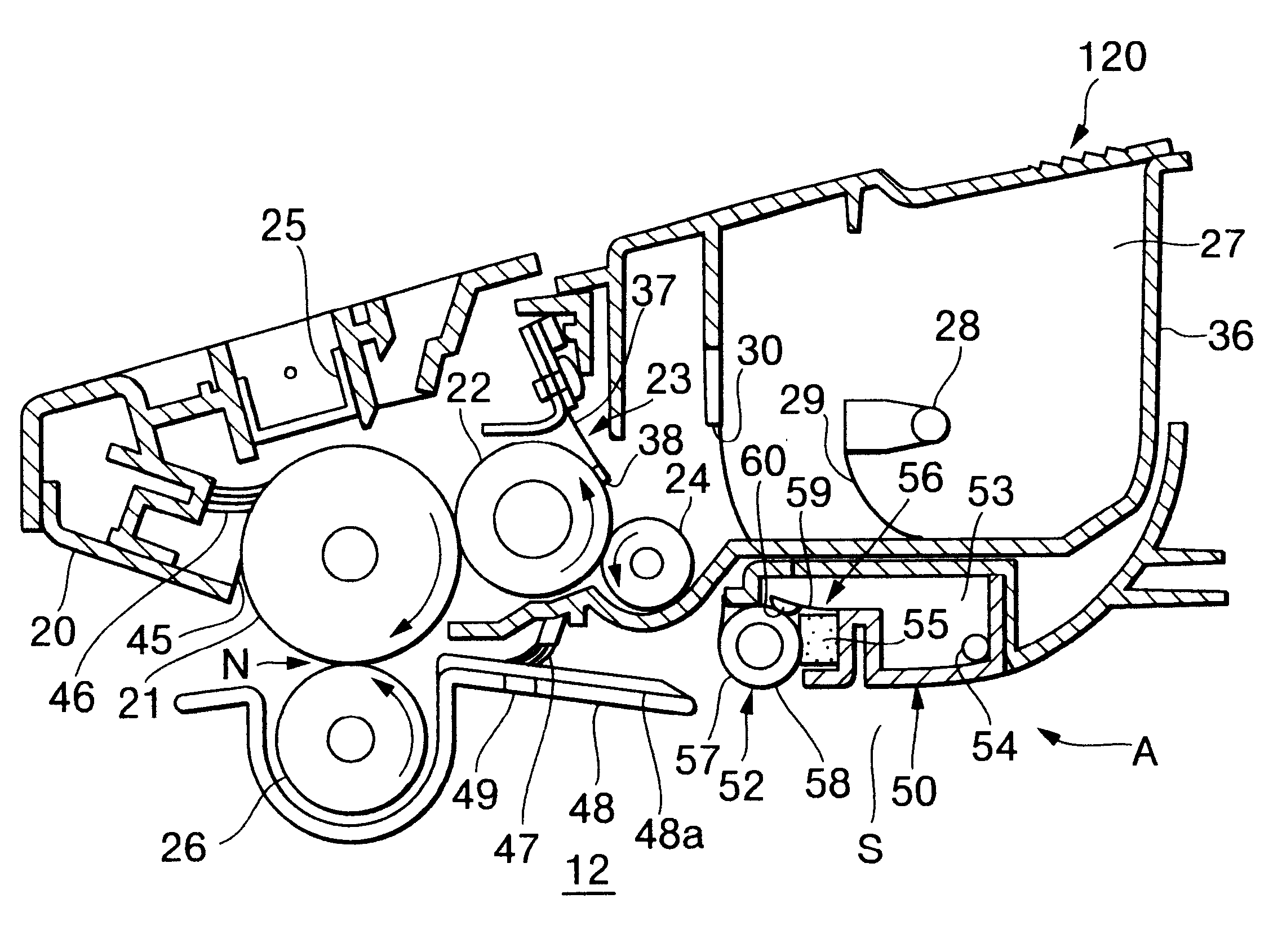
Contrarily, according to the present embodiment, as shown in FIGS. 8 and 9, the image forming unit 12 is made from a process cartridge 120 that is detachably mounted to the casing 2.

The process cartridge 120 is constructed from a combination of a drum cartridge 20 and the development cartridge 36. In the drum cartridge 20, the photosensitive drum 21 and the Scorotron charger 25 are mounted. The photosensitive drum 21 is rotatably mounted in the drum cartridge 20. The drum cartridge 20 is detachably mounted to the side wall 36a of the development cartridge 36 so that the photosensitive drum 21 becomes in confrontation with the development roller 22. ...


PUM


Abstract

A first paper-dust removing device is provided to mainly remove pulp fibers of the paper dust. The first paper-dust removing device is located downstream from a transfer position in the photosensitive drum rotating direction. A second paper-dust removing device is provided to mainly remove talc in the paper dust. The second paper-dust removing device may be located downstream from the first paper dust removing device in the photosensitive drum rotating direction or upstream from the transfer position in the sheet conveying direction along the sheet transport path. An additional first paper-dust removing device may be located upstream from the transfer position in the sheet conveying direction along the sheet transport path.

Description

1. Field of the InventionThe present invention relates to an image forming apparatus such as a laser printer.2. Description of Related ArtLaser printers and other image forming apparatuses mainly include: a photosensitive drum, a developing roller, a transfer roller; and a sheet conveying mechanism. The photosensitive drum is formed with an electrostatic latent image on its outer peripheral surface. The developing roller is disposed in confrontation with the photosensitive drum. The developing roller supplies developing agent, such as toner, to the photosensitive drum, thereby developing the electrostatic latent image into a visible image. The transfer roller is disposed at a transfer position in confrontation with the photosensitive drum. The transfer roller is applied with a transfer bias voltage with a polarity opposite to that of the photosensitive drum. The sheet conveying mechanism conveys a sheet of paper along a sheet transport path in a paper conveying direction toward the ...

Claims


Application Information

Patent Timeline
Patent Type & Authority Patents(United States)
IPC IPC(8): G03G21/00G03G21/18
CPCG03G21/0064G03G21/1814G03G2221/0068G03G2215/00708G03G2221/0042G03G2215/00607
Inventor SATO, SHOUGOFUWAZAKI, TAKESHI
Owner BROTHER KOGYO KK
Why Eureka
Try Eureka