Solenoid valve

a solenoid valve and valve body technology, applied in the direction of valve details, valve arrangement, spindle sealing, etc., can solve the problems of large control force, adverse effect of line pressure on valve member valves, etc., and achieve the effect of fewer components, simple design and easy assembly

Inactive Publication Date: 2003-01-14
MKS INSTR INC
View PDF21 Cites 78 Cited by
  • Summary
  • Abstract
  • Description
  • Claims
  • Application Information

AI Technical Summary

Benefits of technology

The valve assembly according to the present disclosure provides all the benefits of prior existing valve assem...

Problems solved by technology

A problem previously encountered with such valves was adverse effects of line pressures on valve members of the valves at or near closure of the members.
Anoth...

Method used


Image

  • Solenoid valve
  • Solenoid valve
  • Solenoid valve

Examples


Embodiment Construction

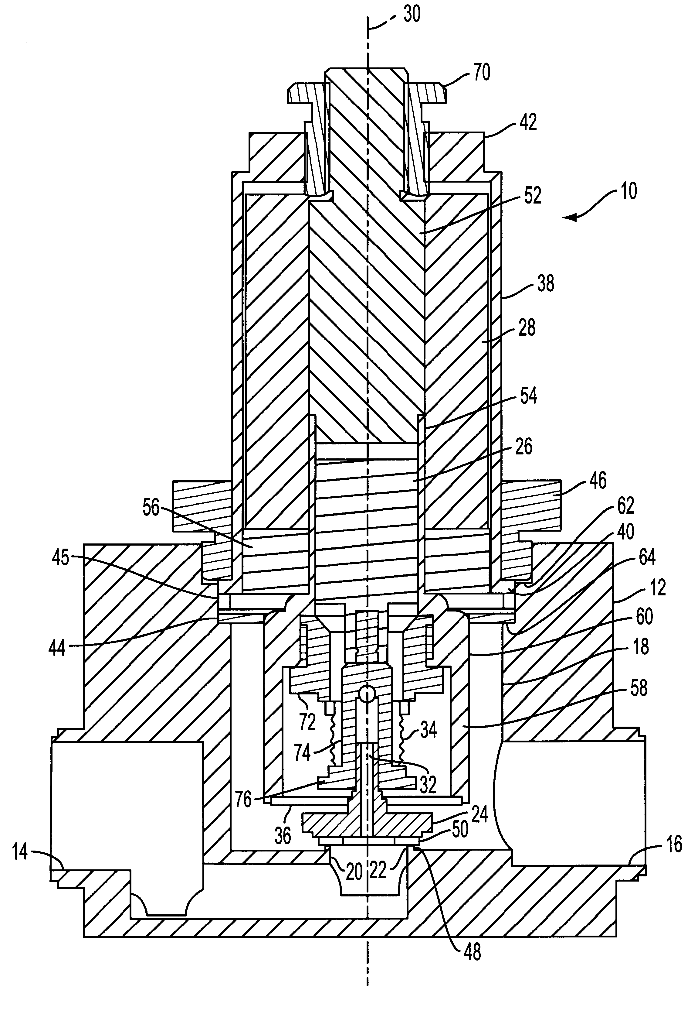
Referring to FIG. 1, the present disclosure provides a precision high flow-rate solenoid valve assembly 10, which is capable of proportional-control of large volumes of fluid in response to relatively low-power electrical control signals. The valve assembly 10 provides all the benefits of prior existing valve assemblies, yet has a simpler design including fewer components that are easier to assemble together during manufacturing.

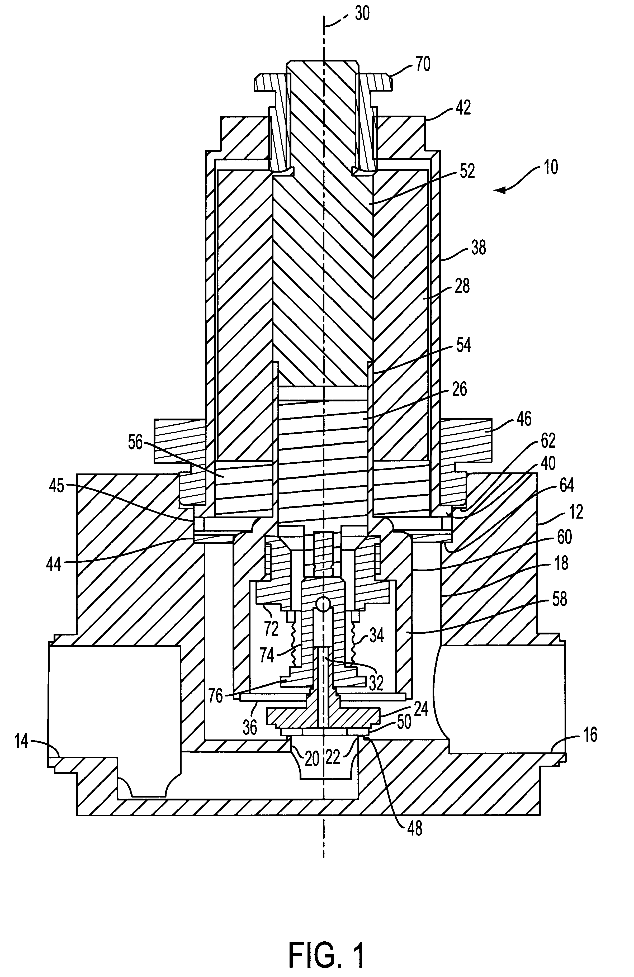
The valve assembly 10 includes a valve body 12 having a fluid inlet port 14, a fluid outlet port 16, a bore 18 connected to one of the inlet and the outlet ports, and a valve seat 20 having a passageway 22 connecting the bore 18 to the other of the inlet and the outlet ports. In the embodiment shown, the bore 18 is connected to the outlet port 16 and the passageway 22 is connected to the inlet port 14. A valve member 24 is received in the bore 18, and an armature 26 of magnetic material is fixed to the valve member 24. An electrical solenoid winding 28 is re...


PUM


Abstract

A valve assembly including a body having an inlet port, an outlet port, and a valve seat having a passageway. An electrical solenoid assembly moves a valve member upon being energized to control fluid flow between the inlet and the outlet ports. The valve assembly also includes a fluid-tight bellows positioned to apply a force to the valve member, and a pressure balancing passageway connects the inlet port to the bellows. The valve assembly further includes a housing received over the solenoid assembly and having a flange received against the valve body. A seal is positioned between the flange of the housing and the valve body, and a collar is secured in a continuous manner to the valve body over the housing flange, thereby securing the housing to the valve body and applying a sealing force to the seal in a substantially even manner.

Description

FIELD OF DISCLOSUREThe present disclosure relates to the field of fluid flow control and, more particularly, to a solenoid valve. Even more particularly, the present disclosure relates to improvements in solenoid-actuated proportional-control valves, and, in one particular aspect, to a unique and advantageous electrically operated fluid valve of low-cost and uncomplicated construction which accurately controls high-volume flows with the aid of a frictionless suspension and a pressure-counterbalancing bellows cooperating with its movable valve member.BACKGROUND OF DISCLOSUREFluid valves exist in a wide variety of forms and sizes, serving a multitude of purposes, handling flowable materials whose characters range from light gaseous to heavy slurries and near-solids, and operable at various speeds under controls as diverse as simple binary (ON-OFF), proportional, direct-manual and remote-electrical. Those which are capable of responding quickly to govern even relatively large flows wit...

Claims


Application Information

Patent Timeline
IPC IPC(8): F16K31/06F16K41/10F16K41/00
CPCF16K41/10F16K31/0693F16K31/06
Inventor ANASTAS, JEFFREY V.
Owner MKS INSTR INC
Why Eureka
Try Eureka