Surface light source device and adjusting method of chromaticity thereof

a surface light source and chromaticity technology, applied in semiconductor devices, lighting and heating apparatus, instruments, etc., can solve problems such as cost and delivery disadvantages, color tone and color tone unevenness, and difficulty in specifying and purchasing led elements of the desired grad

Inactive Publication Date: 2003-01-21
CALLAHAN CELLULAR L L C
View PDF13 Cites 139 Cited by
  • Summary
  • Abstract
  • Description
  • Claims
  • Application Information

AI Technical Summary

Problems solved by technology

Therefore, it has disadvantage in color tone and color tone unevenness as compared with the surface light source device using a cold cathode ray tube lamp.
However, it is difficult to specify and purchase LED elements of the desired grade.
In some case, although it is possible to specify the grade of LEDs to be purchased, it may have disadvantage in cost and delivery.
However, when the device is only formed of only the "b" graded elements and the "a" and "c" graded elements are disused.
Manufacture cost increases as a whole.

Method used


Image

  • Surface light source device and adjusting method of chromaticity thereof
  • Surface light source device and adjusting method of chromaticity thereof
  • Surface light source device and adjusting method of chromaticity thereof

Examples


first embodiment

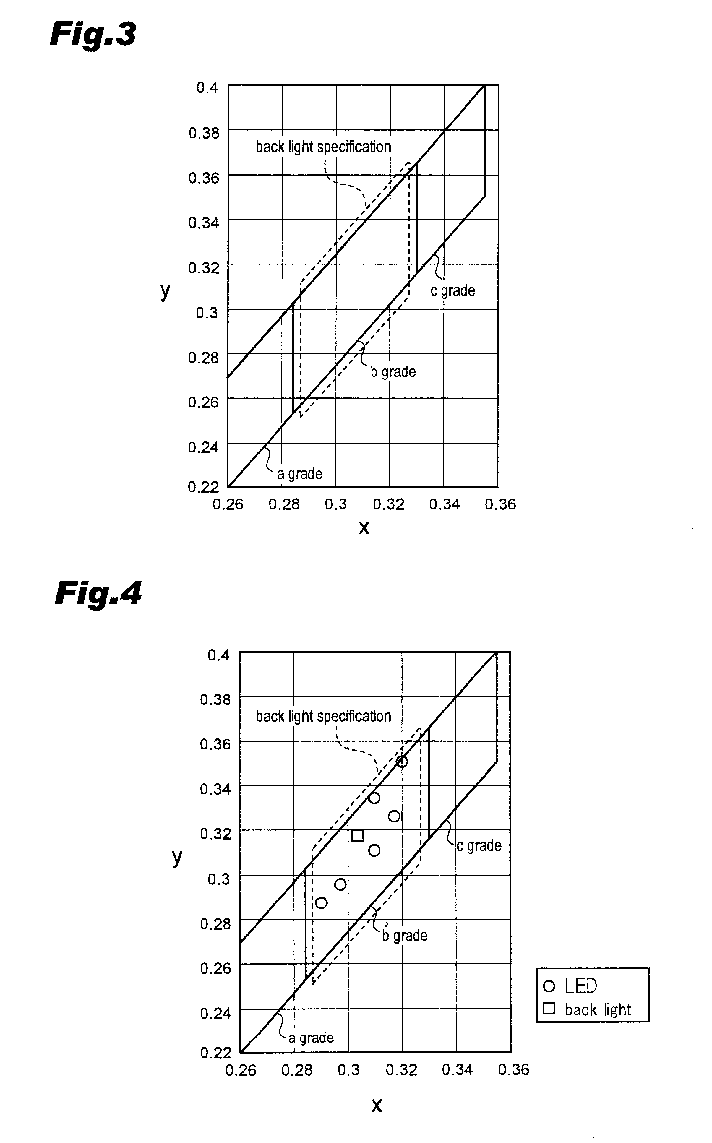
The surface light source device of the first embodiment is formed by using six white LED elements only of the "b" grade as the point light sources 2. Color tone of the surface light source device is shown in FIG. 4. ".smallcircle." in the diagram indicates chromaticity of each of the six white LED elements, and ".quadrature." indicates chromaticity of the surface light source when the surface light surface device is formed by the six white LED elements. As shown in FIG. 4, all of the white LED elements are classified in the "b" grade and the chromaticity on the surface light source satisfies the specification.

Explanation on the surface light source device comprising four white LED elements of the "b" grade, one white LED element respectively of the "a" and "c" grades.

second embodiment

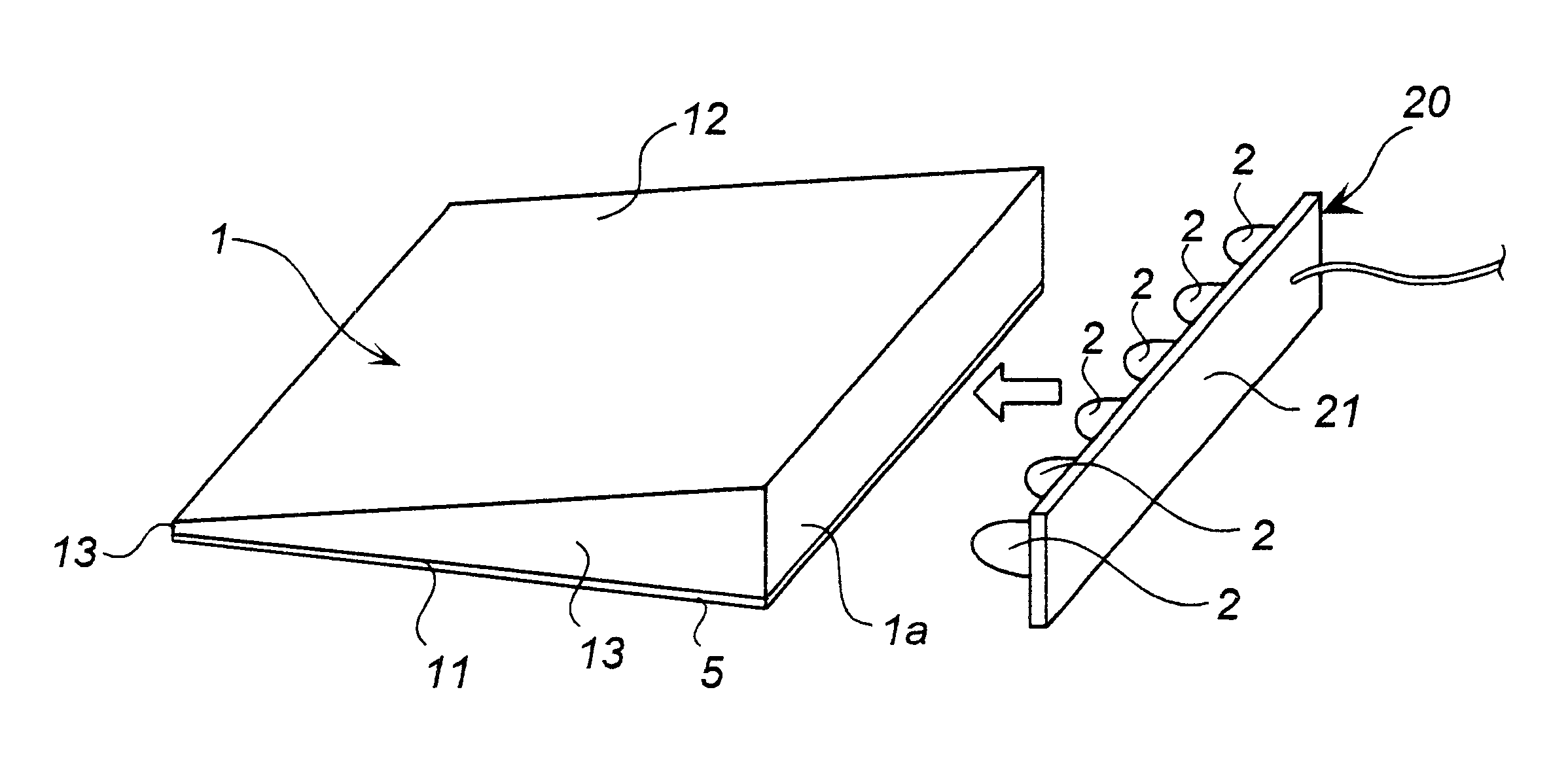
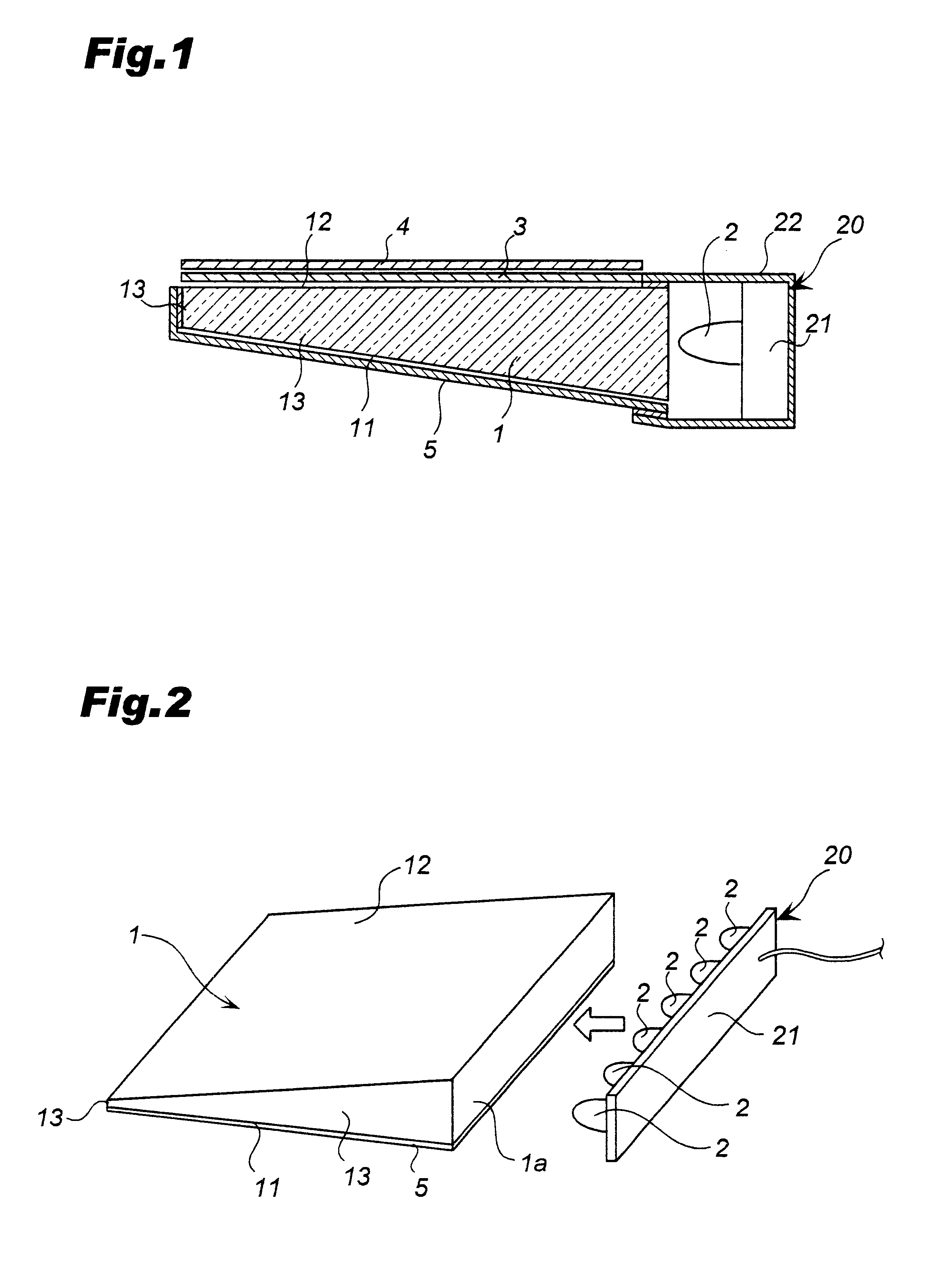
The LED elements on the LED substrate 21 is arranged in an order of the grades b, a, b, b, c, b from a left side as shown in Table 1, and the surface light source device of the second embodiment is formed.

FIG. 5 illustrates chromaticity of each of white LED elements and chromaticity of a surface light source of the surface light source device of a second embodiment. In this diagram, ".smallcircle." indicates chromaticity of each of the six white LED elements, and ".quadrature." is chromaticity on the surface light source formed by the white LED elements. As shown in FIG. 5, chromaticity of the surface light source in this structure satisfies the specification.

However, as shown in FIG. 6, yellowish color tone unevenness is observed on a right side where the white LED element of the "c" grade is arranged and degrades the quality of the surface light source.

Then, a surface light source device in this embodiment is formed by preparing white LED elements of approximately equal chromatici...


PUM

PropertyMeasurementUnit
thicknessaaaaaaaaaa
areaaaaaaaaaaa
thicknessaaaaaaaaaa

Abstract

In this surface light source device, light is incident from a plurality of point light sources 2 arranged on a one side end surface of a light guide plate 1, is reflected on a light reflecting surface 11 on a rear surface of the light guide plate 1, and is emitted from a front surface of the light guide plate 1. The point light sources 2 comprise white light emitting diode elements. Two white light emitting diode elements out of six of the white light emitting diode elements having chromaticity outermost from a center of an aimed chromaticity range in opposite hue directions are arranged in an approximately center of a group of the white diode elements.

Description

1. Field of the InventionThis invention relates to a surface light source device comprising an aggregate of point light sources comprising light emitting elements such as an LED mainly used for a back light of a liquid crystal display panel, and an adjusting method of chromaticity thereof.2. Description of Prior ArtAn edge light type surface light source using a translucent flat plate as a light guide plate is well known as a surface light source for a backlight of a liquid crystal display panel. In such the surface light source, light is incident from one side end surface (an edge part) of a light guide plate of a translucent parallel flat plate or a wedge-shaped flat plate, and the incident light is diffused uniformly to an entire area of the light guide plate. A part of the diffused light is turned into diffused reflected light by a light reflecting member on a rear surface of the light guide plate, and the diffused light is emitted from a front surface of the light guide plate.T...

Claims


Application Information

Patent Timeline
Patent Type & Authority Patents(United States)
IPC IPC(8): F21V8/00G02F1/1335G02B6/00
CPCG02B6/0068F21Y2101/00F21Y2105/00Y10S362/812G02B6/0048F21Y2115/10G02F1/1335
Inventor KUWABARA, SATOSHIYAMASHITA, HIROSHIYAMAMURA, TORUNISHIDA, NOBUHITOOCHIIWA, MASASHISATOU, MICHIAKI
Owner CALLAHAN CELLULAR L L C
Why Eureka
Try Eureka