
High density packaging for multi-disk systems

a multi-disk system and high density technology, applied in the direction of electrical apparatus casings/cabinets/drawers, furniture parts, instruments, etc., can solve the problems of physical arrangement and storage of office computing equipment in a limited amount of space, tower type packaging that is often not very space efficient, and is not stackabl

Inactive Publication Date: 2003-01-21
ORACLE INT CORP
View PDF13 Cites 89 Cited by
  • Summary
  • Abstract
  • Description
  • Claims
  • Application Information

AI Technical Summary

Benefits of technology

The solution provides a compact, high-density storage system that maximizes space efficiency, supports multiple low-profile drives, and ensures reliable operation with redundant power and cooling, facilitating the integration of various server functions within a single field-replaceable unit.

Problems solved by technology

One problem facing many office computing environments is how to physically arrange and store office computing equipment in a limited amount of space.
Conventional server systems are often packaged in tower type chassis that are often not very space efficient.
Such chassis are typically not stackable and may require a large amount of clearance for fan airflow, etc.
However, an office may not be able to readily obtain all of its server needs in this form factor, or at the very least, its choice for file servers, email servers, web servers, network servers, etc., may be restricted if they are limited to this form factor.
Furthermore, with the increasing miniaturization of components, the 1.75 inch height unit of the current industrial standard racks may be an inefficient use of space.

Method used


Image

  • High density packaging for multi-disk systems
  • High density packaging for multi-disk systems
  • High density packaging for multi-disk systems

Examples


Embodiment Construction

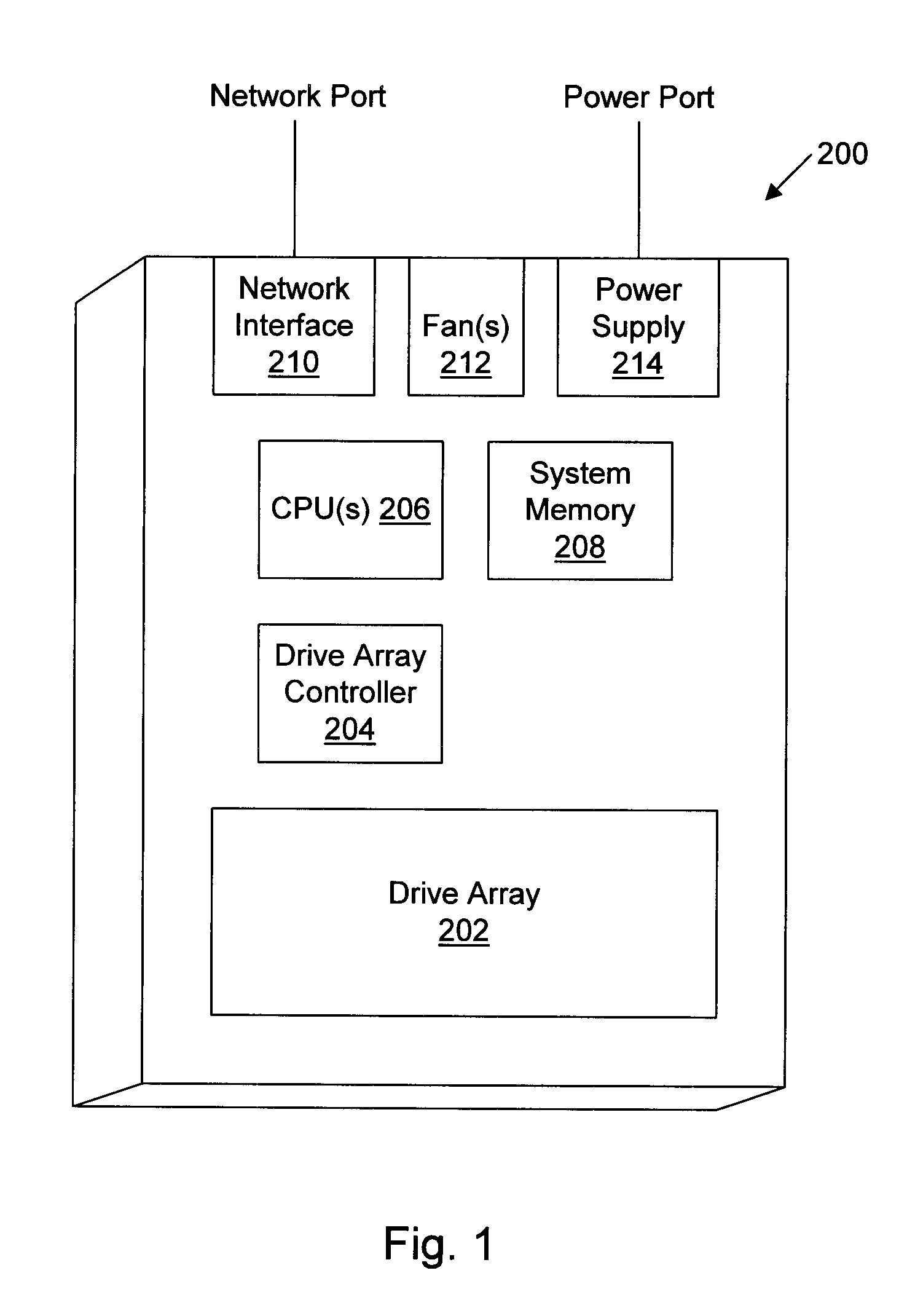
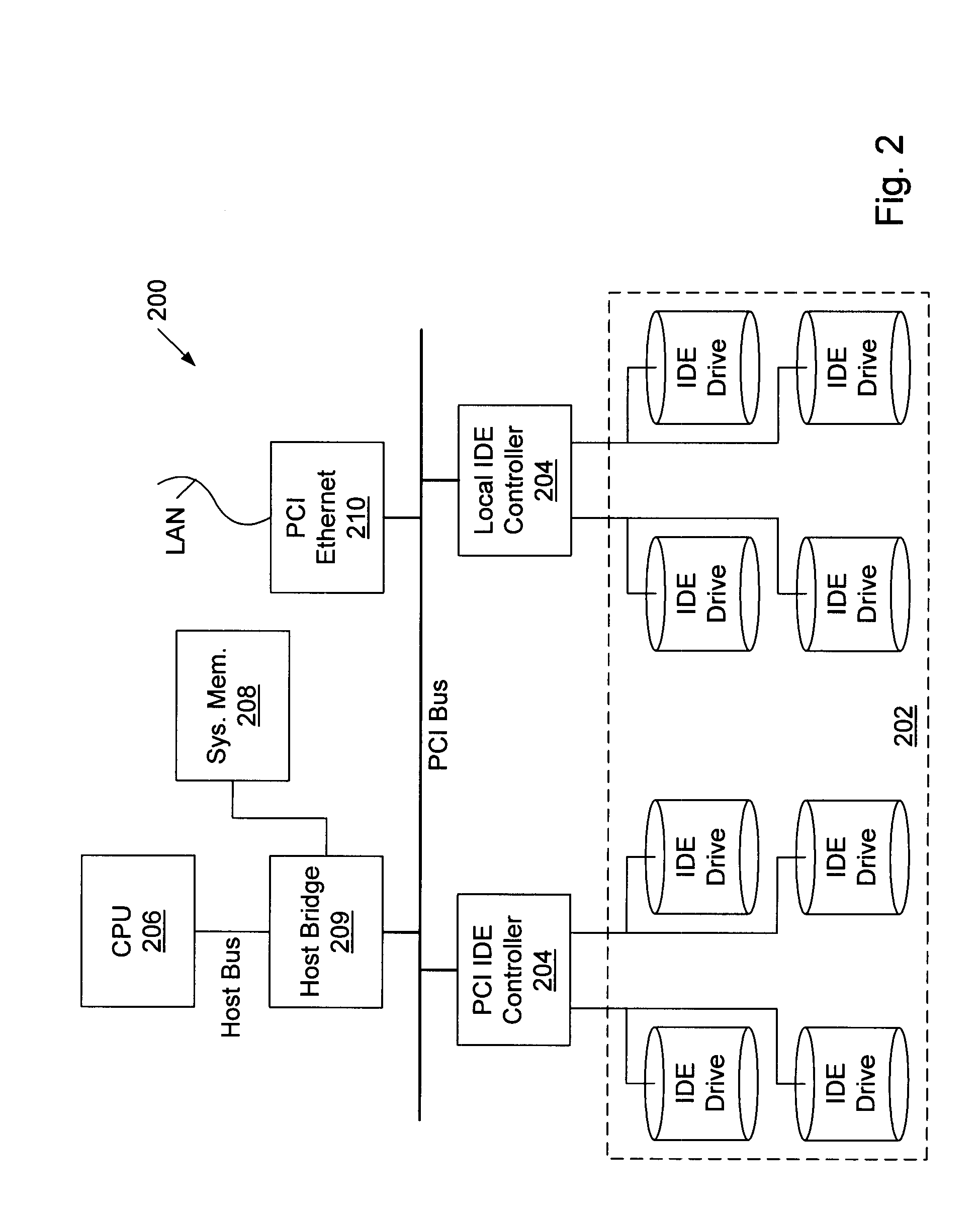
Conventional storage systems are typically designed to allow for replacement or hot swapping of most essential components, such as disk drives, fans, power supplies, etc. In contrast, FIG. 1 illustrates a storage system 200 assembled as a field replaceable unit, according to one embodiment. The entire system 200 may be a single field replaceable unit (FRU). Storage system 200 may include multiple individual disk drives to provide a large storage capacity which is implemented as a single field replaceable unit. Since there are no or a reduced number of field replaceable or hot swappable internal parts, storage system 200 may have a storage density that is not possible with storage systems that support field or hot replacement of components, such as disk drives.

Storage system 200 includes a drive array 202. Drive array 202 may include multiple hard disk drives. Each hard disk drive is configured within system 202 so as not to be individually replaceable in the field. Thus, the drives ...


PUM

PropertyMeasurementUnit
thickaaaaaaaaaa
voltagesaaaaaaaaaa
heightaaaaaaaaaa

Abstract

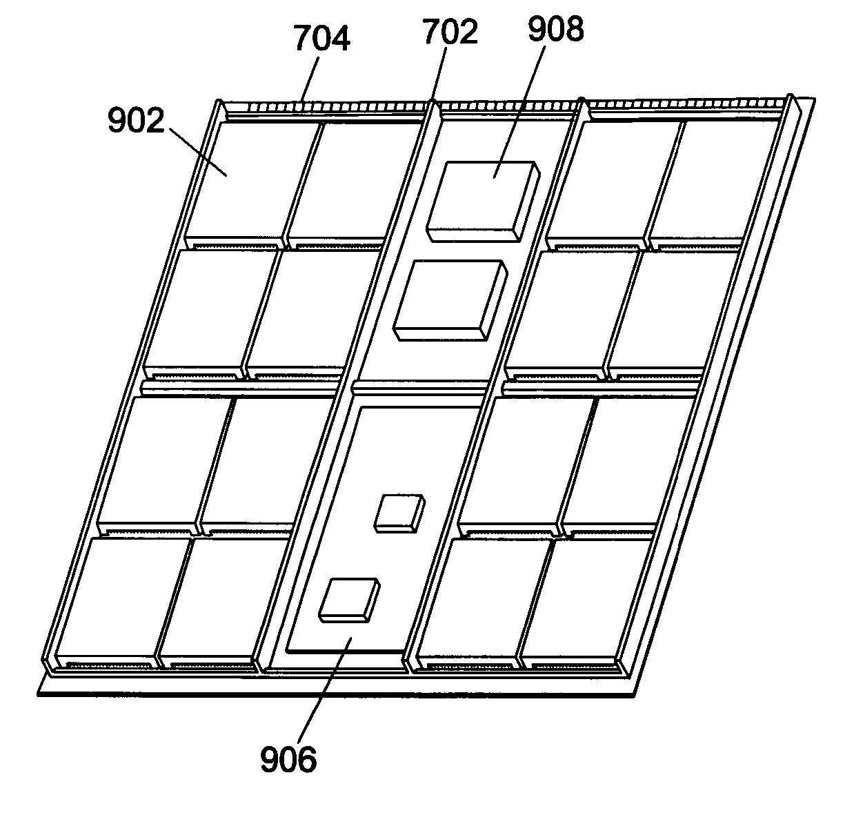
A substrate for packaging a storage or server system may include one or more sections of the substrate configured to hold a two-dimensional array of disk drives. Another section of this substrate may be configured to hold circuitry for accessing the array of disk drives. This circuitry may include one or more processors. The substrate also includes a first plurality of ribs positioned in the first access of the substrate. The first plurality of ribs separate the sections from one another. The section configured to hold the control circuitry may also be configured to hold one or more power supplies for supplying power to the array of disk drives and control circuitry. This section, as well as other sections, may be divided in two by one or more additional ribs in a transverse direction. The substrate may be configured to be mounted in a cage or rack and may include an edge connector at one edge of the substrate to provide electrical connectivity to a back plane in the cage or rack. A lateral protrusion may extend along each parallel edge of the substrate for mounting the substrate in the cage or rack by sliding the substrate into the cage or rack.

Description

1. Field of the InventionThis invention relates to the packaging of storage and / or server equipment, and more particularly a low profile tray for multi-disk storage or server systems and an enclosure for such trays.2. Description of the Related ArtOne problem facing many office computing environments is how to physically arrange and store office computing equipment in a limited amount of space. Typically, an office may have a central computing room in which most of the office server systems are located. Naturally, it is desirable for such computer rooms to require as little real estate as possible. Conventional server systems are often packaged in tower type chassis that are often not very space efficient. Such chassis are typically not stackable and may require a large amount of clearance for fan airflow, etc. Some computer environments employ racks to mount computer systems in a more space efficient manner. A standard-industrial 19 inch rack is often used. The current 19 inch indu...

Claims


Application Information

Patent Timeline
Patent Type & Authority Patents(United States)
IPC IPC(8): G11B33/12
CPCG11B33/125
Inventor LEE, WHAY S.TALAGALA, NISHAWU, CHIA Y.CHONG, JR., FAYRETTBERG, RANDALL D.
Owner ORACLE INT CORP
Learn More