Dynamic video communication evaluation equipment

Inactive Publication Date: 2003-01-28
YOKOGAWA ELECTRIC CORP
View PDF11 Cites 9 Cited by
  • Summary
  • Abstract
  • Description
  • Claims
  • Application Information

AI Technical Summary

Problems solved by technology

However, according to this conventional method, the estimation error is not indicated, leading to a problem that a rough estimation value and an estimation value with high precision value are not differentiated from each other.
If a communication cost involved in the transmission of the quality data is required, the communication time and analysis processing time are diversified, leading to various costs necessary for communication costs.
It is a general tendency to obtain a result in small estimation error as the analysis takes time and cost.
There is a case where no correlation exists between the time and cost involved in an analysis and the obtained estimation error.
Accordingly, it is not always expected that the estimation error gradually decreases as the analysis result is obtained later.
Since, however, it is not expected due to the above mentioned limitation either to perform an analysis for a long time to obtain a result with smaller estimation error using multiple analysis processing methods, or to wait for processing results by means of expensive processing method, there was a problem that users could not verify whether the expected analysis result was obtained or not.
Moreover, although for users of the above mentioned dynamic video communication analysis equ

Method used


Image

  • Dynamic video communication evaluation equipment
  • Dynamic video communication evaluation equipment
  • Dynamic video communication evaluation equipment

Examples


Embodiment Construction

A dynamic video communication evaluation equipment according to a preferred embodiment of the present invention will be now described with reference to the attached drawings.

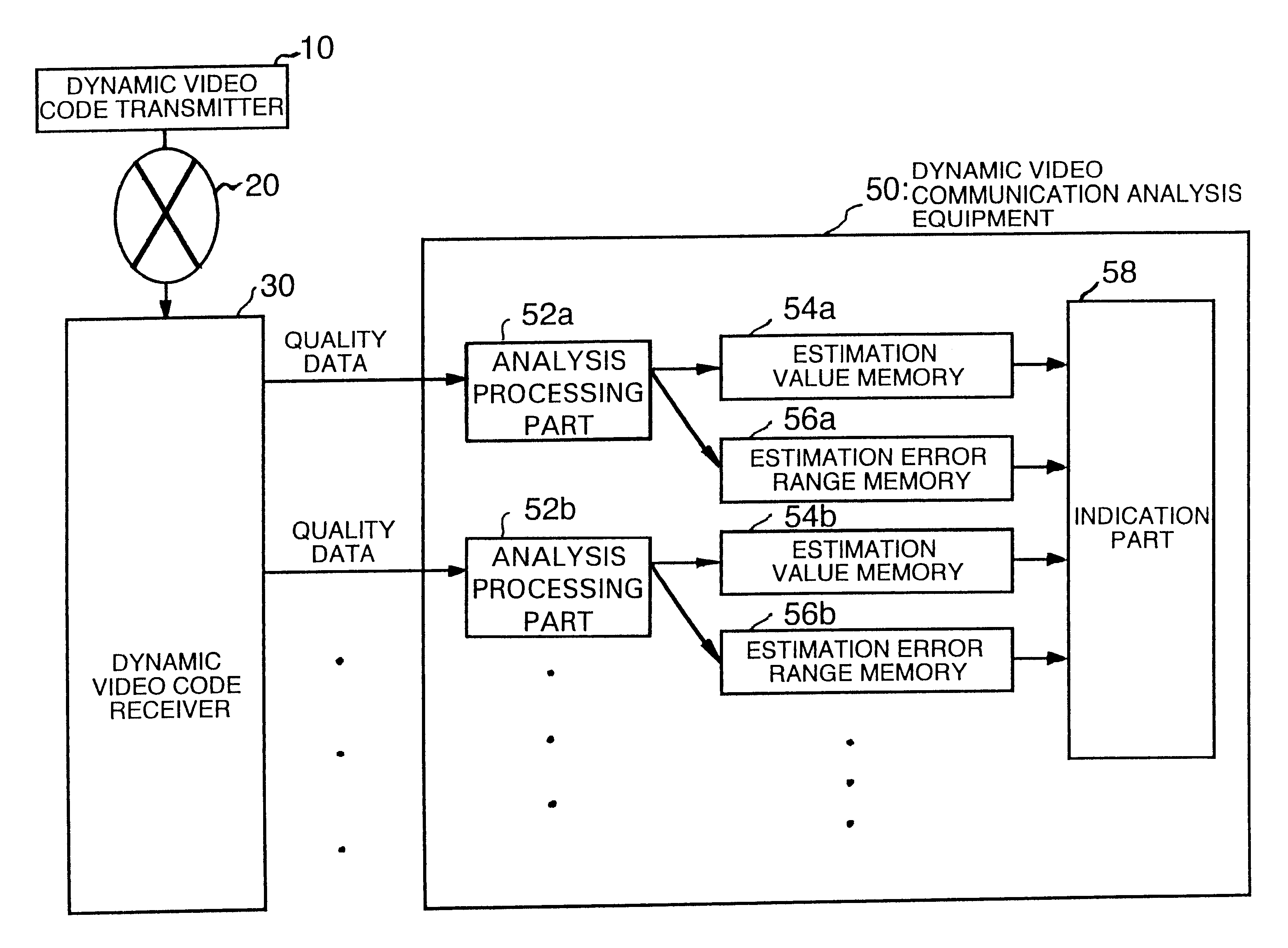
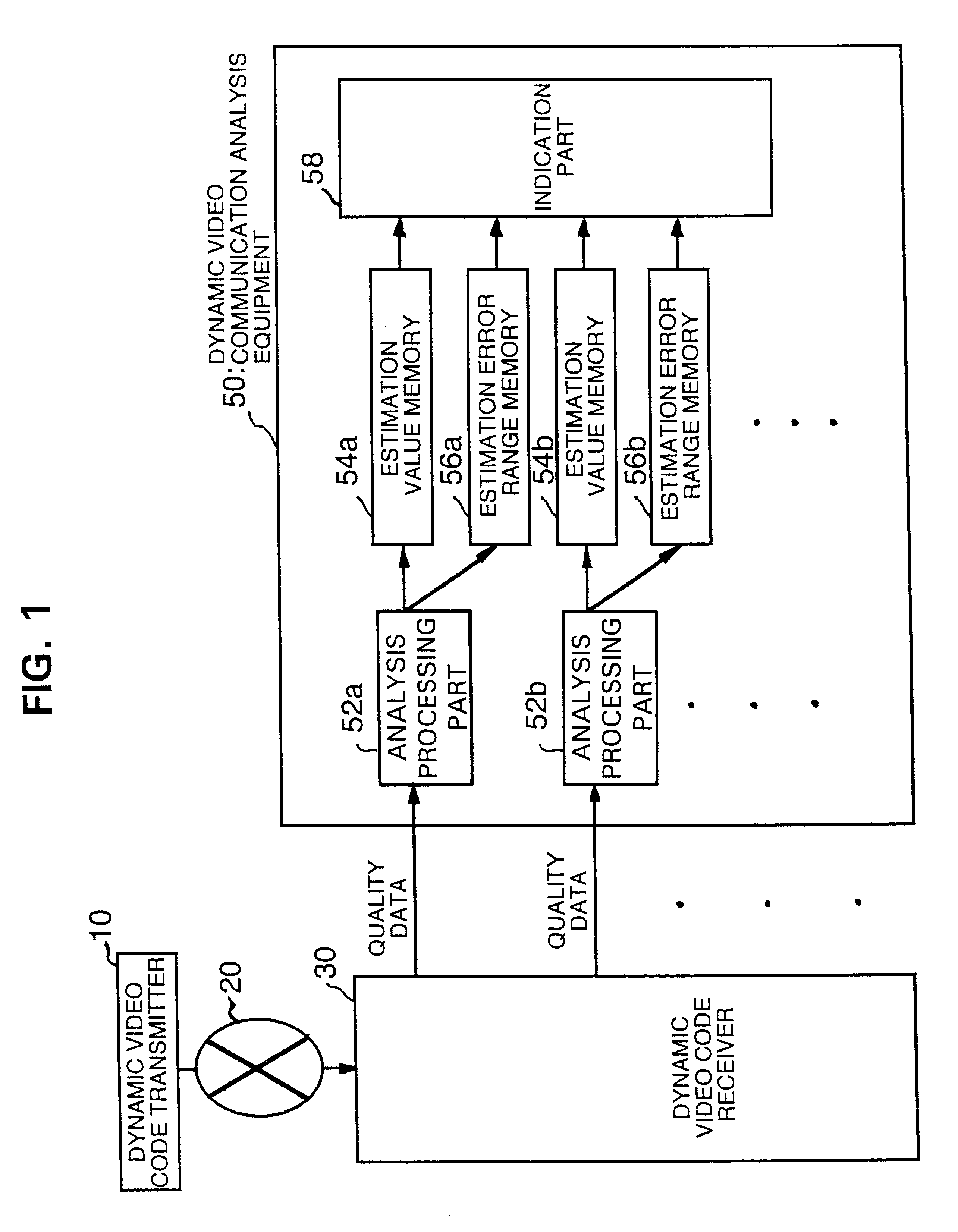
FIG. 1 is a block diagram showing the construction of the dynamic video communication evaluation equipment according to the preferred embodiment of the present invention. The summary of this equipment will be first described.

As shown in FIG. 1, the dynamic video communication evaluation equipment of the present invention comprises a dynamic video code transmitter 10 and a dynamic video code receiver 30 which are respectively connected to a network 20, and a dynamic video communication analysis equipment 50 connected to the dynamic video code receiver 30.

The dynamic video code receiver 30 transmits received dynamic video code and communication protocol data to the dynamic video communication analysis equipment 50 as quality data.

The dynamic video communication analysis equipment 50 includes multiple analysis proc...


PUM


Abstract

In a dynamic video communication evaluation equipment for analyzing codes by multiple methods for evaluating a dynamic video image, an analysis including estimation is performed to fix a reliability of the analysis result, enabling a processing termination in response to the analysis result in view of effective utilization of time or cost. The dynamic video communication evaluation equipment comprises a dynamic video code transmitter which transmits a dynamic video as a digital dynamic video code via a network by selecting it from multiple dynamic video coding methods and multiple communication protocols, a dynamic video code receiver for receiving and decoding the digital dynamic video code which are transmitted via the network conforming to the video coding method and communication protocol used for the digital dynamic video code, and a dynamic video communication analysis equipment composed of analysis means which calculates both of estimation value of dynamic video image quality evaluation value and an error range of said estimation value according to said dynamic video coding method and said communication protocol, and indication means to indicate said estimation value and said error range.

Description

1. Field of the InventionThe present invention relates to a dynamic video communication evaluation equipment, and more particularly to a dynamic video communication evaluation equipment for evaluating dynamic video code and protocol used to transmit and receive digital dynamic video data.2. Description of the Related ArtRecently, wide area computer networks such as Internet have been developed, through which various types of data have been exchanged in a large scale. Conventionally, due to the bottleneck of computer processing speed and lower network throughput, only character information or compressed still video image having comparatively less amount of information were allowed to be exchanged.However, thanks to recent rapid enhancement of the computer processing speed and enhanced network speed, dynamic video image having a large amount of information have become exchanged. Hereafter, it is unavoidable that the dynamic video image will be generally transferred without an analog s...

Claims


Application Information

Patent Timeline
IPC IPC(8): H04N17/00H04L12/00H04N19/00H04L29/06H04N19/102H04N19/146H04N19/159H04N19/196
CPCH04N17/004
Inventor HONDA, YOSHIZOU
Owner YOKOGAWA ELECTRIC CORP
Why Eureka
Try Eureka