Terminal pressure-welding apparatus

a technology of pressure-welding apparatus and clamping rod, which is applied in the direction of soldering apparatus, conductor, and auxillary welding devices

Inactive Publication Date: 2003-02-04
YAZAKI CORP
View PDF19 Cites 8 Cited by
  • Summary
  • Abstract
  • Description
  • Claims
  • Application Information

AI Technical Summary

Benefits of technology

According to the above-described structures of the present invention, the following advantages are provided.
(1) Since the stopping means prevents the first pattern and the second pattern from coming into contact with each other, for example in preparing a pressure-welding work, damage of the patterns can be prevented.
(2) Since the projecting portion projects from the mounting portion toward the displacing member, the first pattern and the second pattern can be more securely prevented from coming into contact with each other, damage of the patterns can be more securely prevented.
(3) Even if the interval between the first pattern and the second pattern has to be changed, since the distance between the abutting plane and the mounting portion, the first pattern and the second pattern can be securely prevented from coming into contact with each other, thereby securely preventing damage of the patterns. And, since the fixing means secures the projecting portion to the mounting portion, the distance between the abutting plane and the mounting portion can be prevented from changing unexpectedly, thereby securing the pressure-welding of the electric wire and the terminal metal fitting.

Problems solved by technology

In such an operation, the crimper is likely to over-drop, thereby causing an abutment of the crimper on the anvil.
This abutment would further cause a breakage of the patterns (i.e. the crimper and the anvil) even in preparation work of adjusting a interval between the crimper and the anvil.

Method used


Image

  • Terminal pressure-welding apparatus
  • Terminal pressure-welding apparatus
  • Terminal pressure-welding apparatus

Examples


Embodiment Construction

)

An embodiment of the present invention will now be described in further detail with reference to the accompanying drawings.

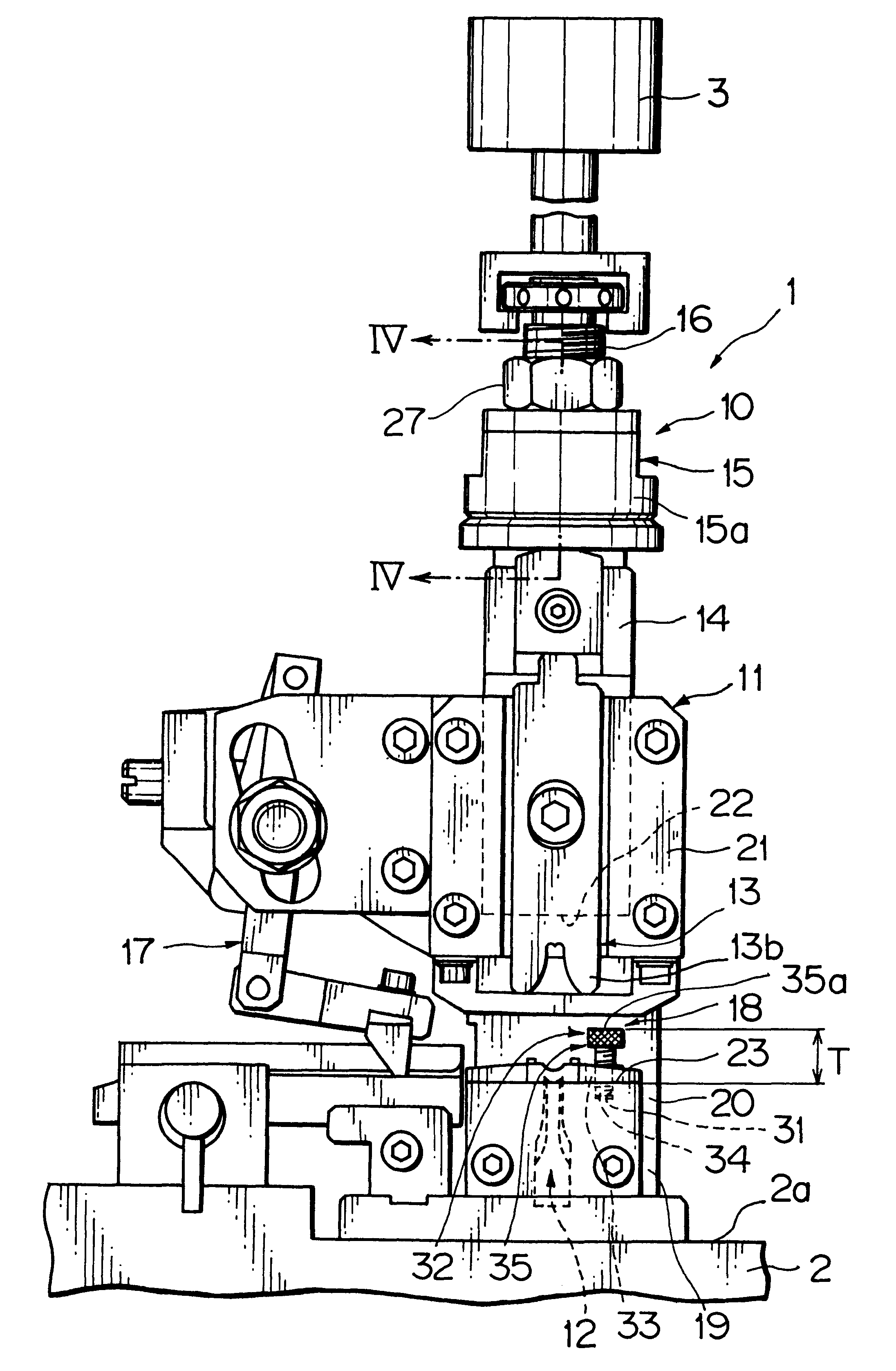
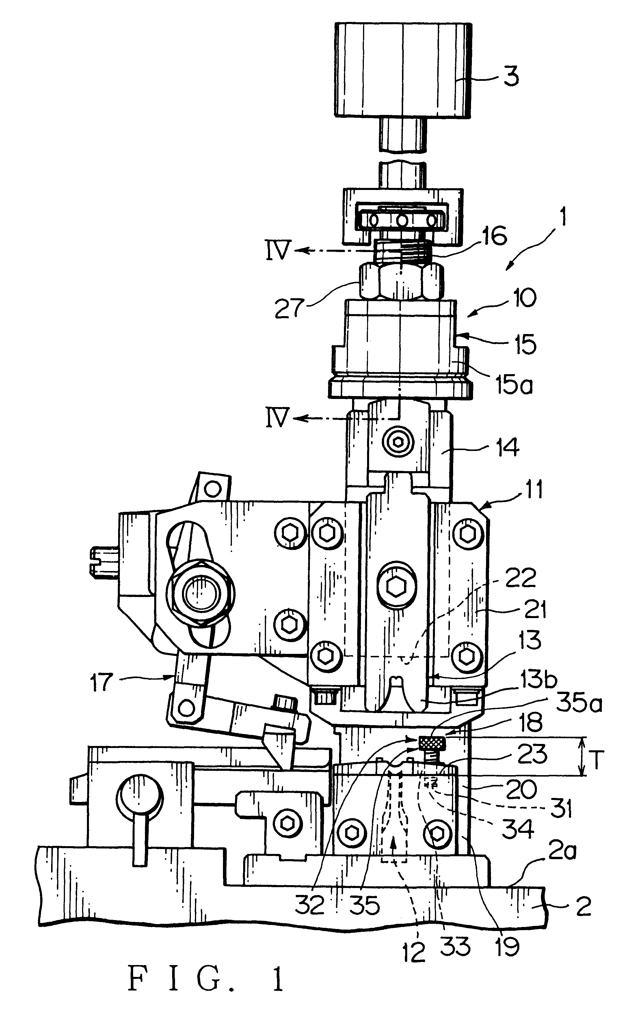
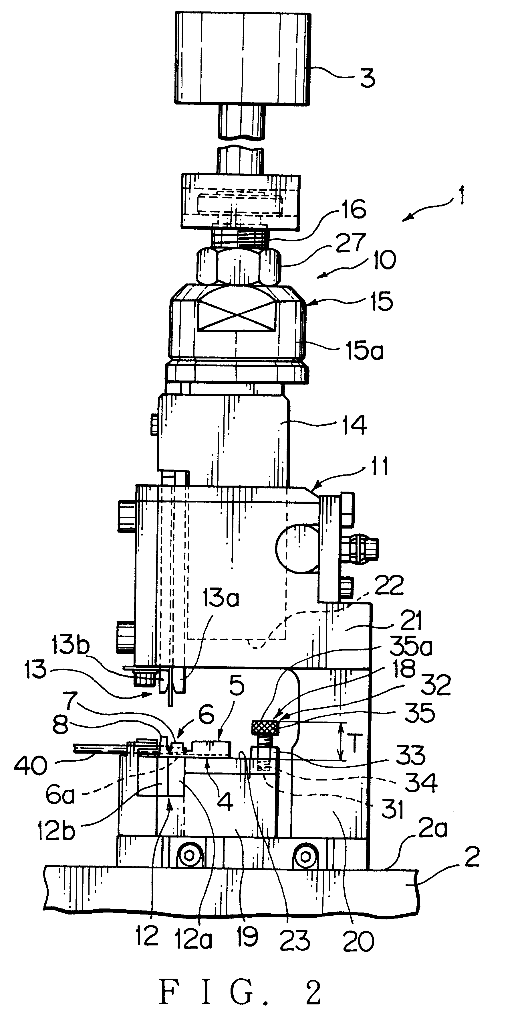
An embodiment of a terminal pressure-welding apparatus in accordance with the present invention is described referring to FIG. 1 to FIG. 6. The terminal pressure-welding apparatus 1 pressure-welds a terminal metal fitting 4 (FIG. 2) to an end portion of an electric wire 40 (FIG. 2), or viceversa, that is, an end portion of an electric wire 40 to a terminal metal fitting 4. The terminal metal fitting 4 is formed of a conductive metal plate and has an electrical contacting portion 5 to which a mating terminal metal fitting is connected and a wire connecting portion 6 to which the electric wire 40 is connected.

The wire connecting portion 6 has a bottom wall 6a on which the electric wire 40 is placed, a pair of conductor crimping pieces 7 continuing from respective edges of the bottom wall 6a, and a pair of sheathing crimping pieces 8 also continuing from the respe...


PUM

PropertyMeasurementUnit
pressureaaaaaaaaaa
pressure forceaaaaaaaaaa
distanceaaaaaaaaaa

Abstract

A terminal pressure-welding apparatus is provided, which includes: a first pattern; a second pattern facing the first pattern, one of the first and second patterns is provided approachably and disapproachably with respect to the other thereof; a mounting portion to mount the other of the first and second patterns; a displacing member carrying the one of the first and second patterns and being movable relatively to the other of the first and second patterns; and a stopping means to check an abutment of the first pattern and the second pattern, wherein a terminal metal fitting and an end portion of an electric wire are placed between the first and second patterns, and the terminal metal fitting and the end portion are pressure-welded by making the first and second patterns approach each other. The stopping means has a projecting portion projecting from the mounting portion toward the displacing member in order to abut against an end plane of the displacing member thereby to check the abutment of the first and second patterns. The projecting portion has an abutting plane to abut against the end plane, an adjusting means of a distance between the abutting plane and the mounting portion, and a fixing means to secure the projecting portion to the mounting portion for keeping the distance.

Description

1. Field of the InventionThe present invention relates to a terminal pressure-welding apparatus to pressure-weld an electric wire and a terminal metal fitting.2. Description of the Related ArtIn electrically connecting an electric wire and a terminal metal fitting to each other by crimping, i.e. by pressure-welding, crimping pieces of the terminal metal fitting, for example, a terminal pressure-welding apparatus shown in Japanese Patent Application Laid-open No. 8-111275 or in Japanese Patent Application Laid-open No. 8-162248 is conventionally used.Each terminal pressure-welding apparatus has an apparatus body secured on the floor or the like of a workshop, a drive source to approach and separate a later-described anvil and a crimper with respect to each other, a pressure-welding device (i.e. applicator) to pressure-weld an electric wire and a terminal metal fitting, and a terminal bundle feeder. The terminal bundle feeder feeds a terminal bundle, i.e. a plurality of terminal metal...

Claims


Application Information

Patent Timeline
Patent Type & Authority Patents(United States)
IPC IPC(8): B23K20/02H01R43/048
CPCB23K20/02B23K2201/38B23K2101/38
Inventor YAMAKAWA, NOBUAKI
Owner YAZAKI CORP
Why Eureka
Try Eureka