Drum brake device

a drum brake and drum technology, applied in the direction of slack adjusters, mechanical devices, fluid-actuated drum brakes, etc., can solve the problems of unavoidable decrease in braking efficiency of conventional drum brakes, and achieve the effect of improving braking efficiency and durability of drum brake devices, and stable automatic shoe clearance adjustment action

Inactive Publication Date: 2003-02-25
NISSHINBO IND INC
View PDF13 Cites 4 Cited by
  • Summary
  • Abstract
  • Description
  • Claims
  • Application Information

AI Technical Summary

Benefits of technology

It is an object of this invention to improve the braking efficiency and the durability of the drum brake device and to attain a stable automatic shoe clearance adjustment action by allowing the pivot section of the pivot lever to swing.
When the brake shoes frictionally engage and interact with the brake drum during braking, the pivot lever is supported by the strut free to swing in order to smoothly move together with the brake shoes, thereby providing a D2L type drum brake device with high braking efficiency despite the use of a single shoe-actuator.
The pivot lever smoothly moves until it contacts with one of brake shoes supported by the anchor, which eliminates overload on the pivot and abutment sections thereof and provides a highly durable device.
When incorporating the automatic shoe clearance adjustment mechanism, no overload is encountered when adjusting. Therefore, operation of the delicate automatic shoe clearance adjustment device, which requires micro-adjustment, may be stabilized.
This invention enables the downsizing of the pivot lever and strut for realizing the drum brake with one shoe-actuator for the service brake, which reduces the cost of manufacturing and the overall weight of the device.
The parking brake mechanism of this invention can easily be installed.

Problems solved by technology

Therefore, the conventional drum brake has an unavoidable decrease in braking efficiency due to the resistance at the sliding portions and the rotational resistance at the pivot sections 61, 61.

Method used


Image

  • Drum brake device
  • Drum brake device
  • Drum brake device

Examples


second embodiment

A second embodiment of this invention is explained with reference to FIGS. 7-9, where the same reference numbers used in the first embodiment will be similarly numbered while the explanation of those components will be omitted.

first embodiment

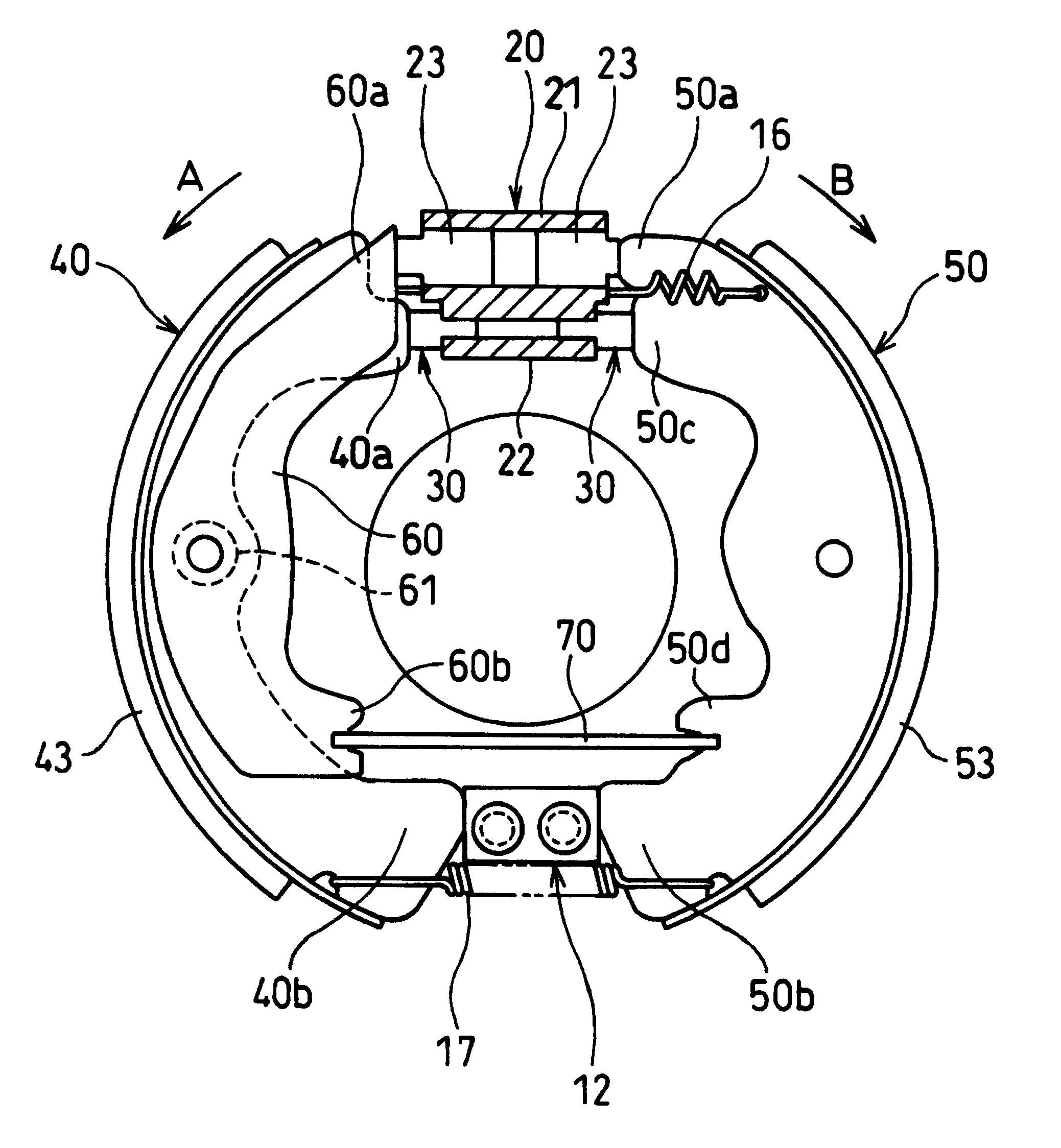
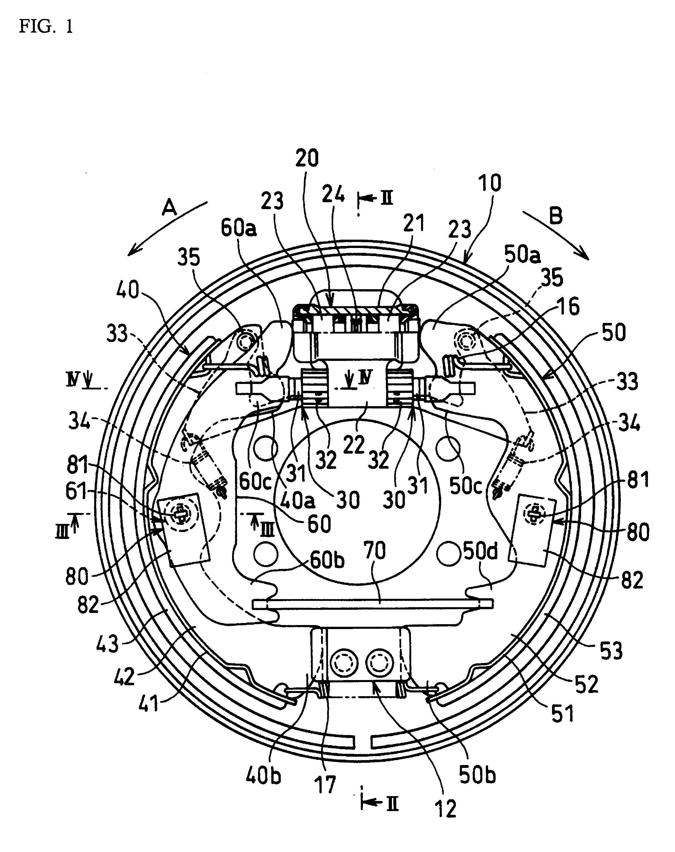
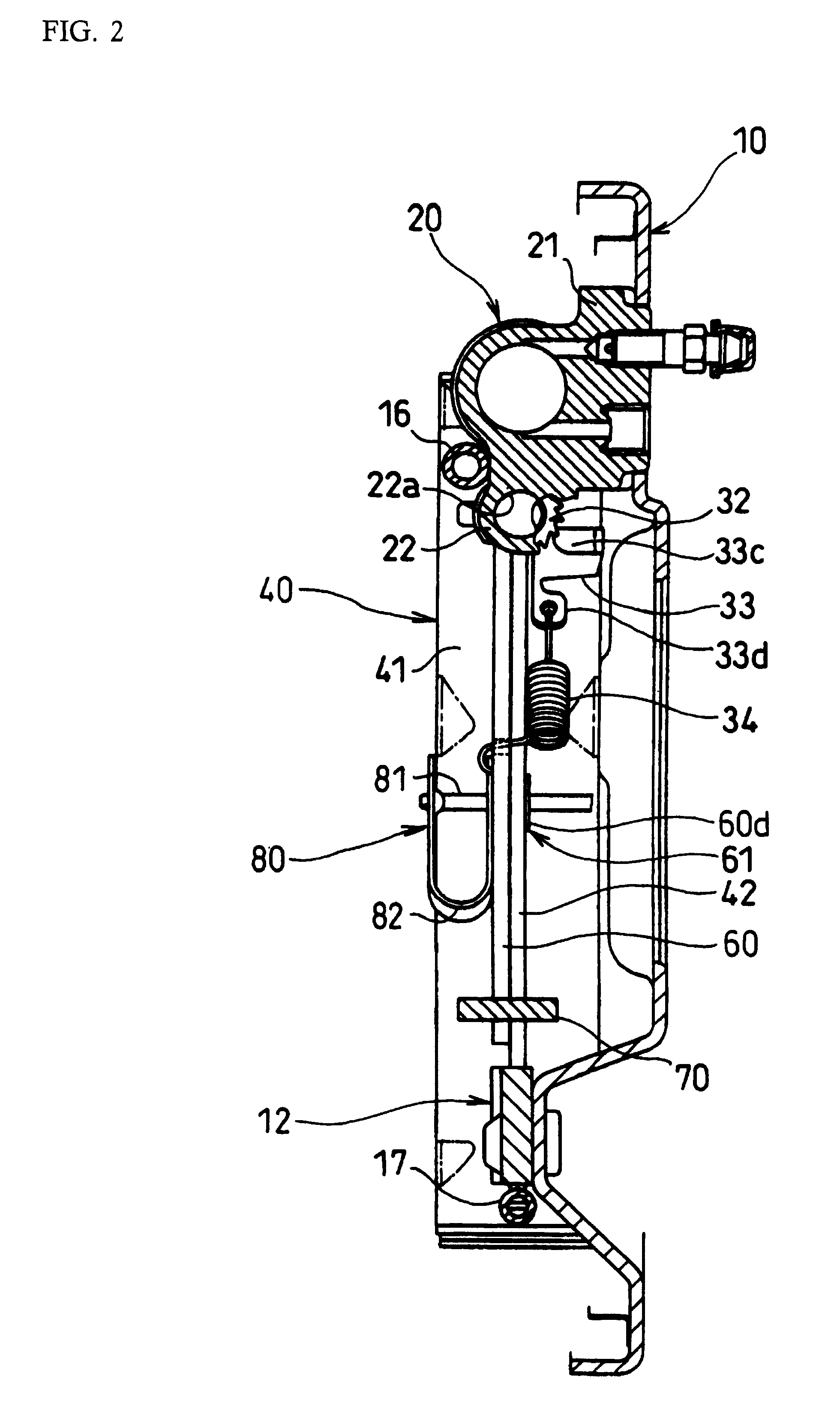
The first embodiment explains the case where the first anchors 30, 30 incorporating the shoe clearance adjustment devices are positioned adjacent to but closer to the brake center than the wheel cylinder 20. In a second embodiment, first anchors 130, 130 are positioned adjacent to but farther away from the brake center than the wheel cylinder 20 as shown in FIG. 7, and a second anchor 112 is incorporated with the automatic shoe clearance adjustment devices.

A shoe expander operable upon activating the parking brake is positioned closer to the brake center than the wheel cylinder 20. Detailed descriptions of the same are explained herein.

An anchor body 122 integrally formed with the cylinder body 21 is positioned adjacent to but farther away from the brake center than the wheel cylinder 20. The anchor body 122 has a horizontal through bore 122a formed therein, into which heads 137, 137 are fit respectively, thereby constituting the first anchors 130, 130. The upper adjacent ends 40a, ...


PUM


Abstract

This invention provides a duo-two leading type drum brake device which simplifies a drum brake structure as well as improves a transmission efficiency of a application force from a shoe actuator to brake shoes. A pivot lever 60 has an intermediate portion pivotally supported on the brake shoes 40. A shoe-actuator 20 is positioned adjacent to the first anchors 30, 30 and being disposed between the ends 60a, 50a of the pivot lever 60 and the other brake shoe 50. A strut 70 is positioned between and functionally engaged with the other ends 60b, 50b of the pivot lever 60 and the other brake shoe 50. An application force of the shoe actuator 20 is transmitted to the brake shoe 40 via a pivot section of the pivot lever 70 and transmitted to the other brake shoe 50 directly from the shoe-actuator 20 and indirectly via the strut 70.

Description

This invention relates to a drum brake device with a single service brake shoe-actuator, intended in particular to provide a braking force equivalent to that of duo-two leading (hereinafter "D2L") type drum brake with two service brake shoe-actuators.DESCRIPTION OF THE PRIOR ARTA drum brake device with a single shoe-actuator capable of providing a braking force equivalent to that of a D2L type drum brake device is disclosed by this applicant in the Japanese Patent Laid-Open Provisional Publication No. 10-47396.This conventional drum brake device is briefly explained with reference to FIG. 10. In this drum brake device, first anchors 29, 29 are positioned between adjacent ends 40a, 50a of a pair of brake shoes 40, 50, and second anchors 11, 11 incorporating shoe clearance adjustment devices are provided between the other ends 40b, 50b of the brake shoes 40, 50. Further, pivot levers 60, 60 are pivotally mounted on intermediate portions of the brake shoes 40, 50; adjacent ends 60a, 60...

Claims


Application Information

Patent Timeline
Patent Type & Authority Patents(United States)
IPC IPC(8): F16D65/38F16D65/22F16D65/09F16D65/04F16D65/16F16D65/56F16D65/14F16D51/00F16D51/52F16D51/30
CPCF16D51/52F16D65/091F16D65/22F16D65/565F16D65/563F16D2125/64F16D2121/02F16D2121/14F16D51/30
Inventor IKEDA, TAKASHI
Owner NISSHINBO IND INC
Why Eureka
Try Eureka