System for assembling substrates to bonding zones provided with cavities

a technology of substrate and cavity, which is applied in the direction of microstructure, decorative arts, chemical vapor deposition coating, etc., can solve the problems of increasing the number of steps in the process, insufficient precision for adjusting the spacing between substrates, and inducing a higher assembly cos

Inactive Publication Date: 2003-03-11
COMMISSARIAT A LENERGIE ATOMIQUE ET AUX ENERGIES ALTERNATIVES
View PDF9 Cites 13 Cited by
  • Summary
  • Abstract
  • Description
  • Claims
  • Application Information

AI Technical Summary

Problems solved by technology

Although the assembly technique using beads made of meltable material is practical to use, its precision remains insufficient for adjusting a spacing between substrates which is less than or equal

Method used


Image

  • System for assembling substrates to bonding zones provided with cavities
  • System for assembling substrates to bonding zones provided with cavities
  • System for assembling substrates to bonding zones provided with cavities

Examples


Embodiment Construction

The aim of the present invention is to propose a substrate and, more generally, a substrate assembly system without the limitations described above.

One of its specific aims is to propose a substrate and an assembly system not requiring additional processing operations.

Another aim is to propose an assembly system that is inexpensive to produce and implement.

A further aim is to propose an assembly system and method making it possible to adjust, simply and with great precision, the spacing between substrates, particularly spacing less than 15 .mu.m.

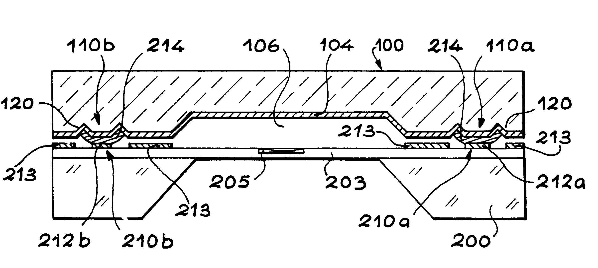
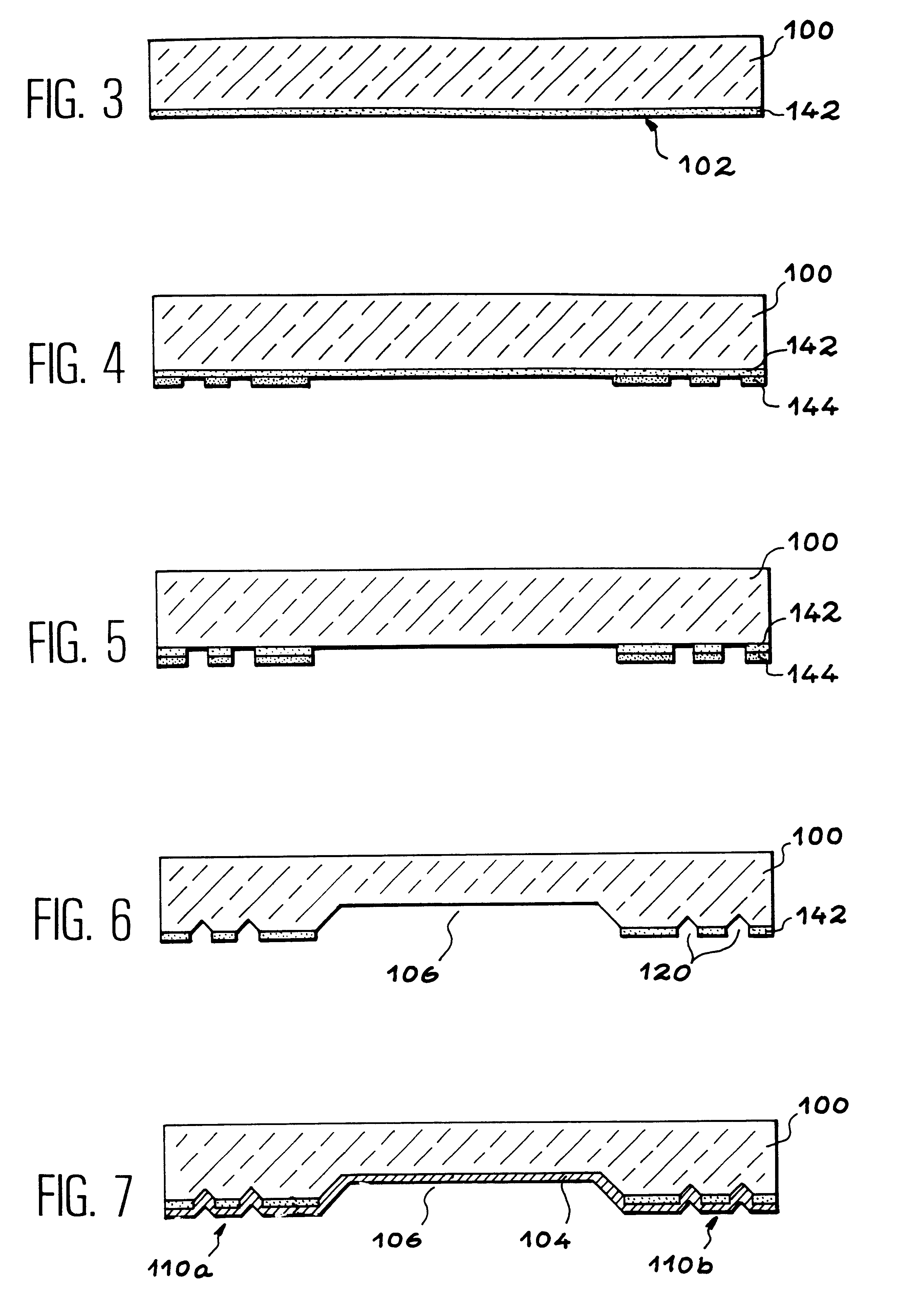
To achieve these aims, the invention more specifically relates to a system comprising a first substrate with at least one bonding area, liable to be assembled with a second substrate, the bonding area comprising an area made of a material that can be wetted with a meltable material. In addition, according to the invention, the bonding area comprises at least one cavity to receive meltable material.

According to the present invention, the term...


PUM

PropertyMeasurementUnit
Areaaaaaaaaaaa
Heightaaaaaaaaaa

Abstract

The invention relates to a system comprising a first substrate (100) with at least one bonding area (110a, 110b), liable to be assembled with a second substrate (200), the bonding area (110a, 110b) comprising an area made of a material (104) that can be wetted with a meltable material. According to the invention, the bonding area (110a, 110b) comprises at least one cavity (120) to receive meltable material.

Description

The present invention relates to a substrate assembly system, using a meltable material.Substrates may be assembled by means of meltable material by placing the substrates to be assembled into contact, heating a meltable material previously positioned in mutual bonding areas of the substrates and leaving said material to cool to solder the bonding areas together.The invention may be applied to the production of electronic devices, particularly ultrahigh frequency circuits.In ultrahigh frequency circuits, the invention may be implemented to attach a cover to the components. Such a cover is particularly intended to favour signal propagation and form a shield against parasitic electromagnetic radiation.More generally, the invention may also be applied to the production of devices including microelectronic and / or micromechanical components requiring a shielding or protective part.For example, the invention may be used in the production of accelerometers including an electronic measureme...

Claims


Application Information

Patent Timeline
IPC IPC(8): B81B7/00H01L21/02H01L23/58H01L21/50H01L23/10H01L23/552H01L23/66H01L23/02B81C1/00
CPCB81B7/0064B81C1/00269H01L21/50H01L23/10H01L23/66H01L23/552B81C2203/019Y10T428/12396H01L2924/1617Y10T428/12347Y10T428/12528
Inventor BALERAS, FRAN.CEDILLA.OISRENARD, PIERRE
Owner COMMISSARIAT A LENERGIE ATOMIQUE ET AUX ENERGIES ALTERNATIVES
Why Eureka
Try Eureka