
Rotary electric machine stator having individual removable coils

a technology of electric machines and stators, which is applied in the direction of dynamo-electric machines, electrical apparatus, magnetic circuit stationary parts, etc., can solve the problems of generating vibration and noise, machine cannot be repaired on site, and must be returned to the manufacturer, so as to reduce the number of bearings and reduce the cost of the machine

Inactive Publication Date: 2003-03-11
MOTEURS LEROY SOMER
View PDF36 Cites 46 Cited by
  • Summary
  • Abstract
  • Description
  • Claims
  • Application Information

AI Technical Summary

Benefits of technology

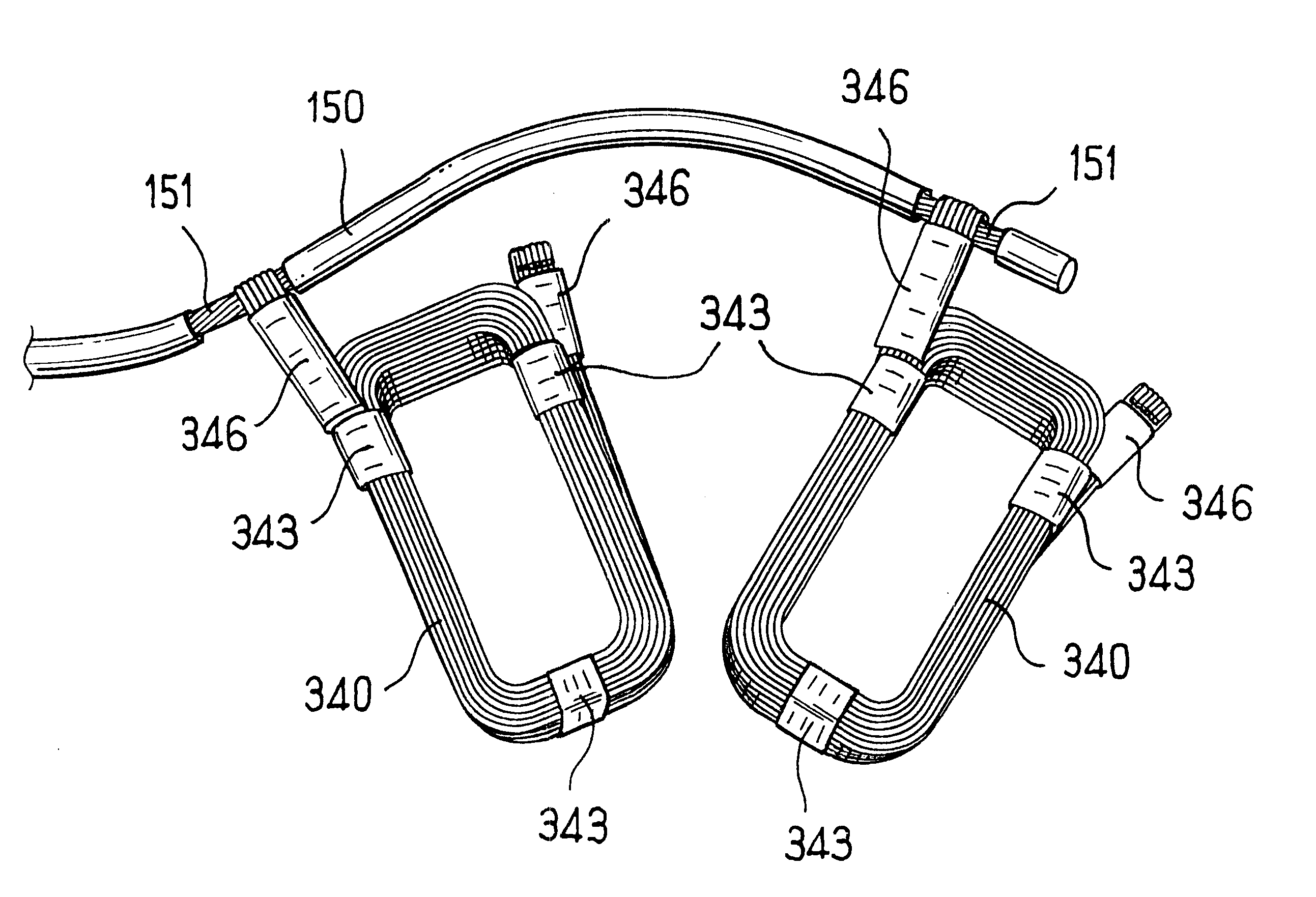
The use of individual coils as defined above, in combination with sheathed electric cables, makes the machine easier to build and maintain. In particular, a coil can easily be replaced without having to return the machine to the manufacturer, thereby making it possible to reduce the period of time in which the installation associated with the machine is out of service.
Such a structure also enables the cost of the machine to be reduced since the number of teeth and the number of coils is relatively small.

Problems solved by technology

This causes the stator to be subjected to mechanical stress tending to ovalize it, thus generating vibration and noise.
Finally, the width of the teeth is constant which gives rise to at least two drawbacks: firstly the magnetic material of the stator can become saturated at the roots of the teeth; and secondly replacing a coil requires the stator to be re-impregnated, so as to lock the coil properly in place on the stator, which means that the machine cannot be repaired on site and must be returned to the manufacturer.

Method used


Image

  • Rotary electric machine stator having individual removable coils
  • Rotary electric machine stator having individual removable coils
  • Rotary electric machine stator having individual removable coils

Examples


Embodiment Construction

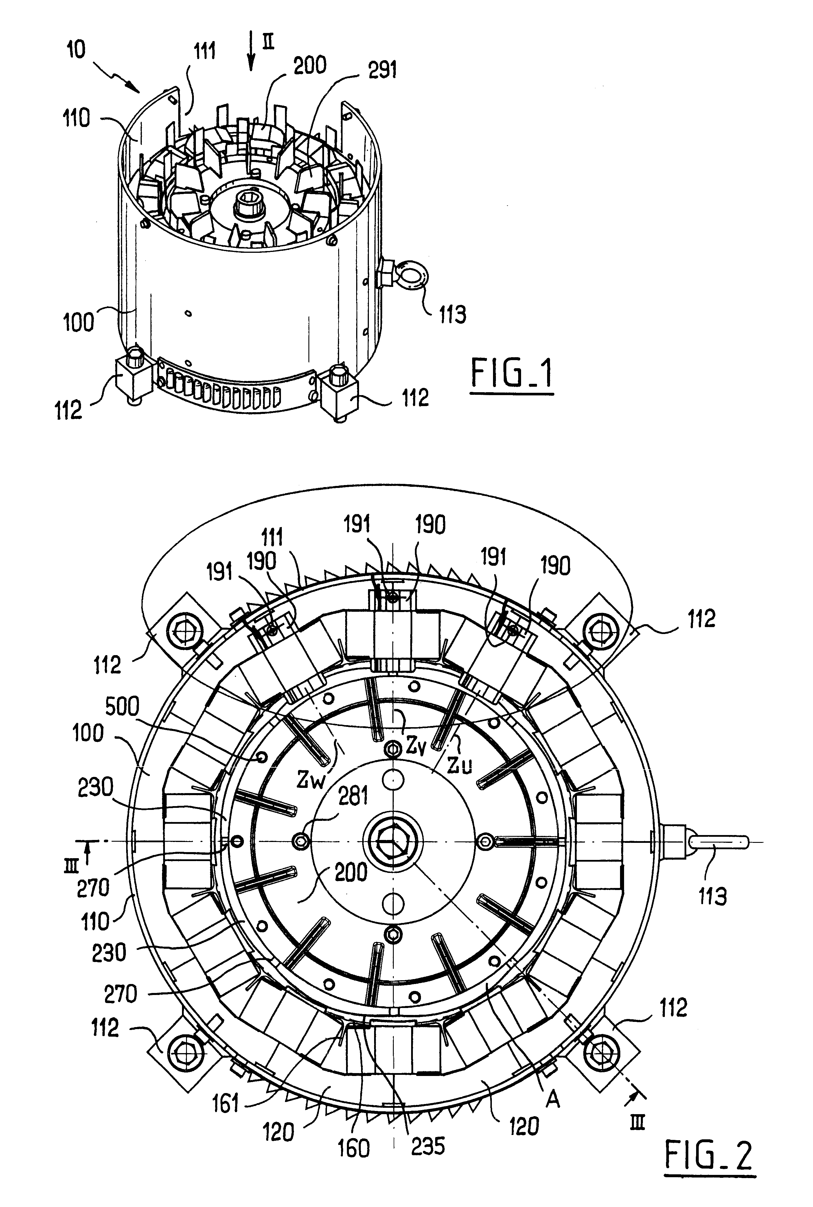
FIGS. 1 and 2 show a synchronous motor 10 of the invention comprising a stator 100 and a rotor 200. The motor 10 is brushless, it has a flux-concentrating rotor, and its stator has windings on teeth, and it operates on three-phase AC.

The stator 100 has a steel case 110 with a lateral opening 111 in particular for passing electrical conductors for powering the stator windings. On the outside, the case is provided with fixing tabs 112 and with a hook 113 for hoisting purposes.

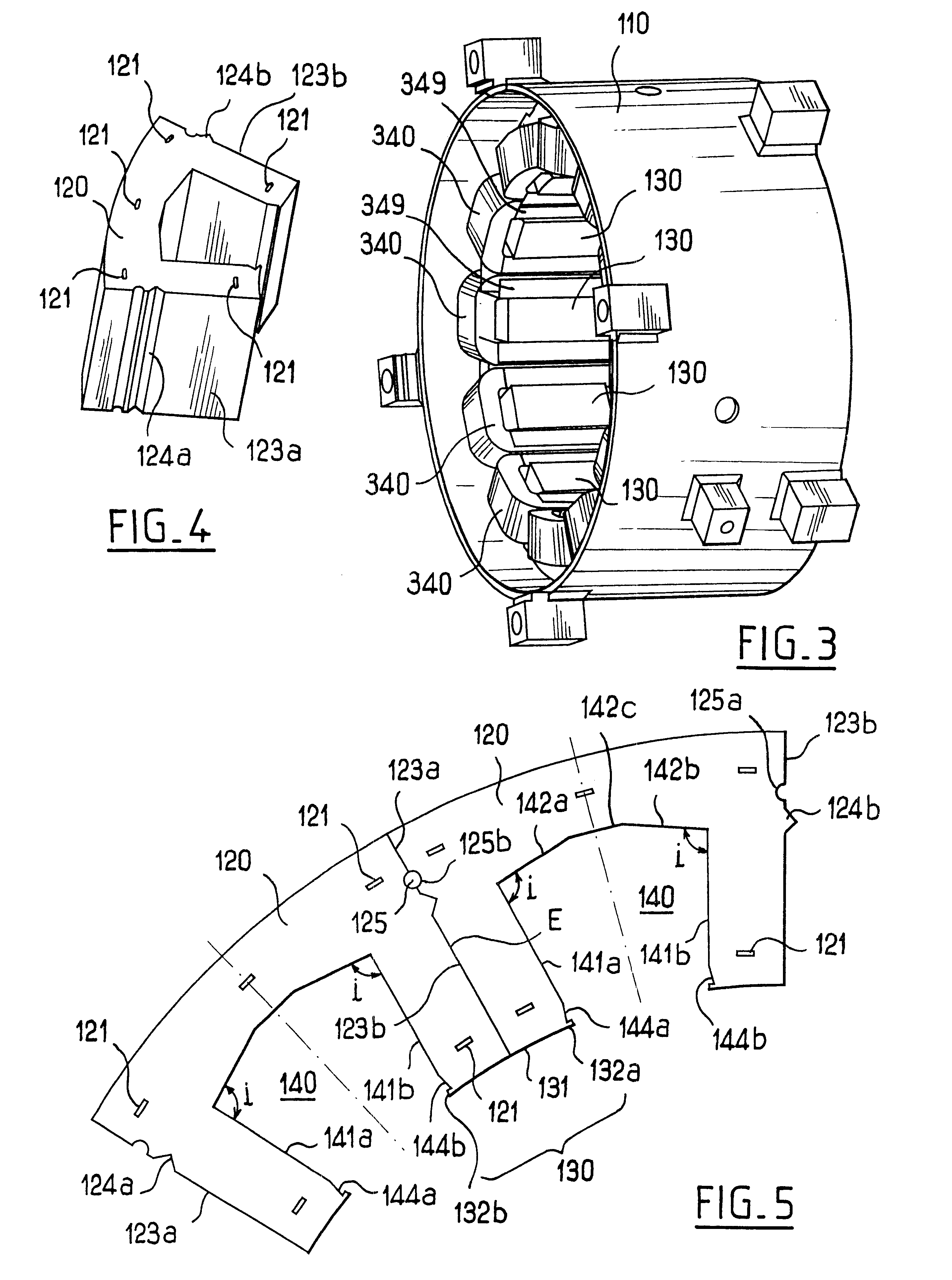
In the example shown, the stator 100 has a magnetic circuit that comprises a plurality of identical sectors 120, one of which is shown in isolation, in perspective in FIG. 4.

Each sector 120 is constituted by a stack of identical magnetic laminations that are superposed and clipped together so as to constitute a unitary assembly, with clipping being obtained using a conventional technique whereby each lamination is subjected to spot deformation at a plurality of assembly points 121. Using a stack of magnetic lamin...


PUM


Abstract

The invention relates to a stator for a rotary electric machine. The stator comprising:a stator magnetic circuit having teeth andindividual coils each engaged on a tooth,each coil including connection ends formed by respective flat bundles of stripped wires curved to form respective hook shapes,the connection ends being soldered to locally stripped portions of sheathed electric cables.

Description

The present invention relates to rotary electric machines and more particularly, but not exclusively, to synchronous motors.European patent application No. EP-A-0 872 943 discloses a rotary electric machine in which the rotor has magnets placed on its surface and the magnetic circuit of the stator receives individual coils. The stator exerts diametrically opposite rotating radial forces on the rotor. This causes the stator to be subjected to mechanical stress tending to ovalize it, thus generating vibration and noise. Finally, the width of the teeth is constant which gives rise to at least two drawbacks: firstly the magnetic material of the stator can become saturated at the roots of the teeth; and secondly replacing a coil requires the stator to be re-impregnated, so as to lock the coil properly in place on the stator, which means that the machine cannot be repaired on site and must be returned to the manufacturer.OBJECTS AND SUMMARY OF THE INVENTIONIn particular, the invention mak...

Claims


Application Information

Patent Timeline
Patent Type & Authority Patents(United States)
IPC IPC(8): H02K3/52H02K3/46H02K3/18H02K15/00H02K1/18H02K3/04H02K15/04
CPCH02K3/18H02K3/522H02K2203/06H02K15/0056
Inventor EYDELIE, ANDREAUGIER, PHILLIPPEGUILLOT, JEAN-MARIE
Owner MOTEURS LEROY SOMER
Learn More