Method and apparatus for testing error detection

a technology for error detection and methods, applied in error detection/correction, emergency protective circuit arrangements, instruments, etc., can solve problems such as present challenges for testing and verification, and the limited effectiveness of arrangement 200, which is useful in many respects, and achieves greater control and focus

Inactive Publication Date: 2003-03-25
SAMSUNG ELECTRONICS CO LTD
View PDF10 Cites 137 Cited by
  • Summary
  • Abstract
  • Description
  • Claims
  • Application Information

AI Technical Summary

Benefits of technology

(2) The present invention is better able to test "comer cases" that arise from "in-flight" operations. In designs employing error correction along with error detection, the initialization-based arrangement can only test a given error condition once, after which the error is typically corrected, never to appear again. The present inventi...

Problems solved by technology

This is especially true for large, complex digital logic circuits, such as processors (including, for example, general purpose microprocessors, mathematical processors or coprocessors, digital signal processors, or other special purpose processors, co...

Method used


Image

  • Method and apparatus for testing error detection
  • Method and apparatus for testing error detection
  • Method and apparatus for testing error detection

Examples


Embodiment Construction

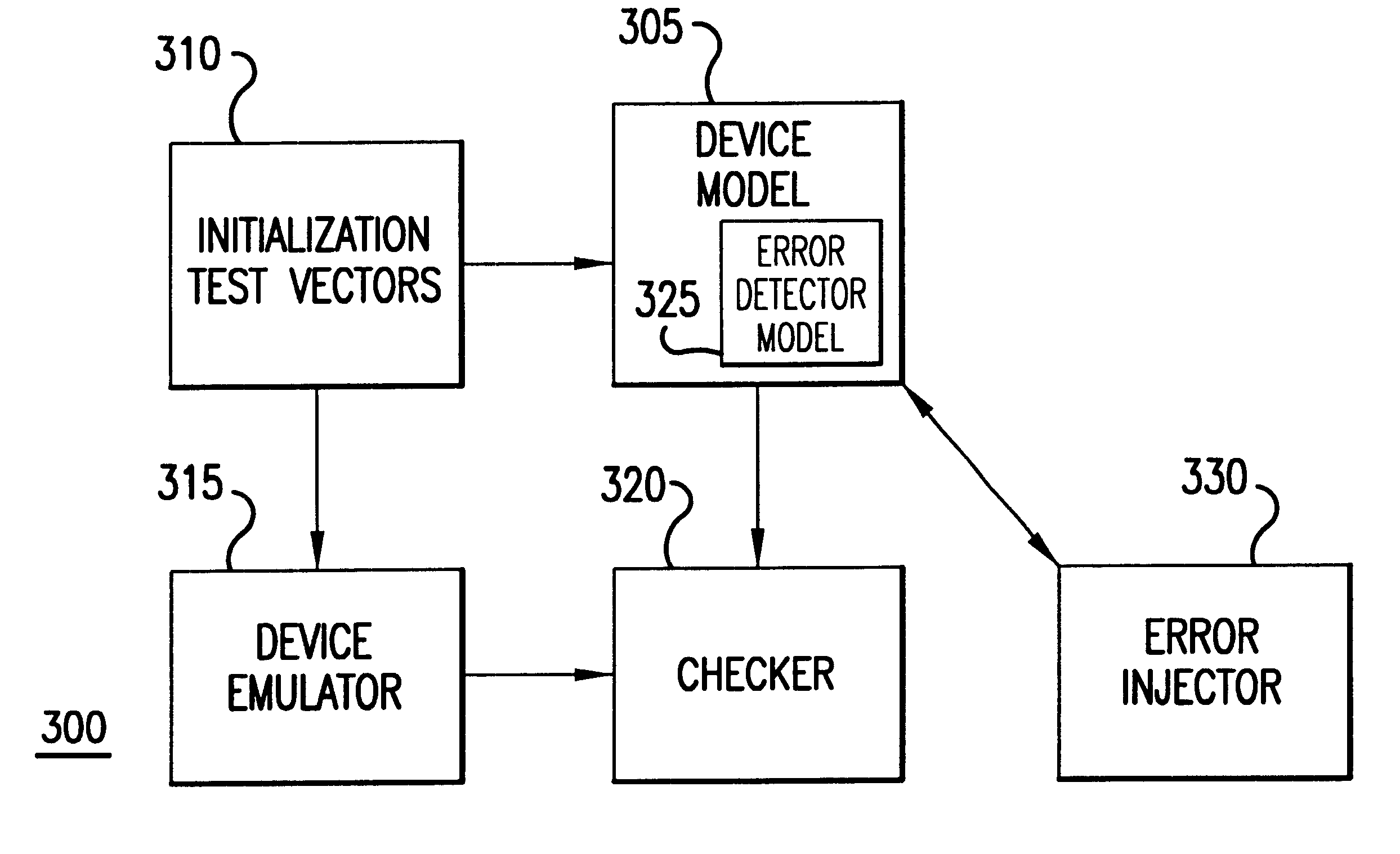
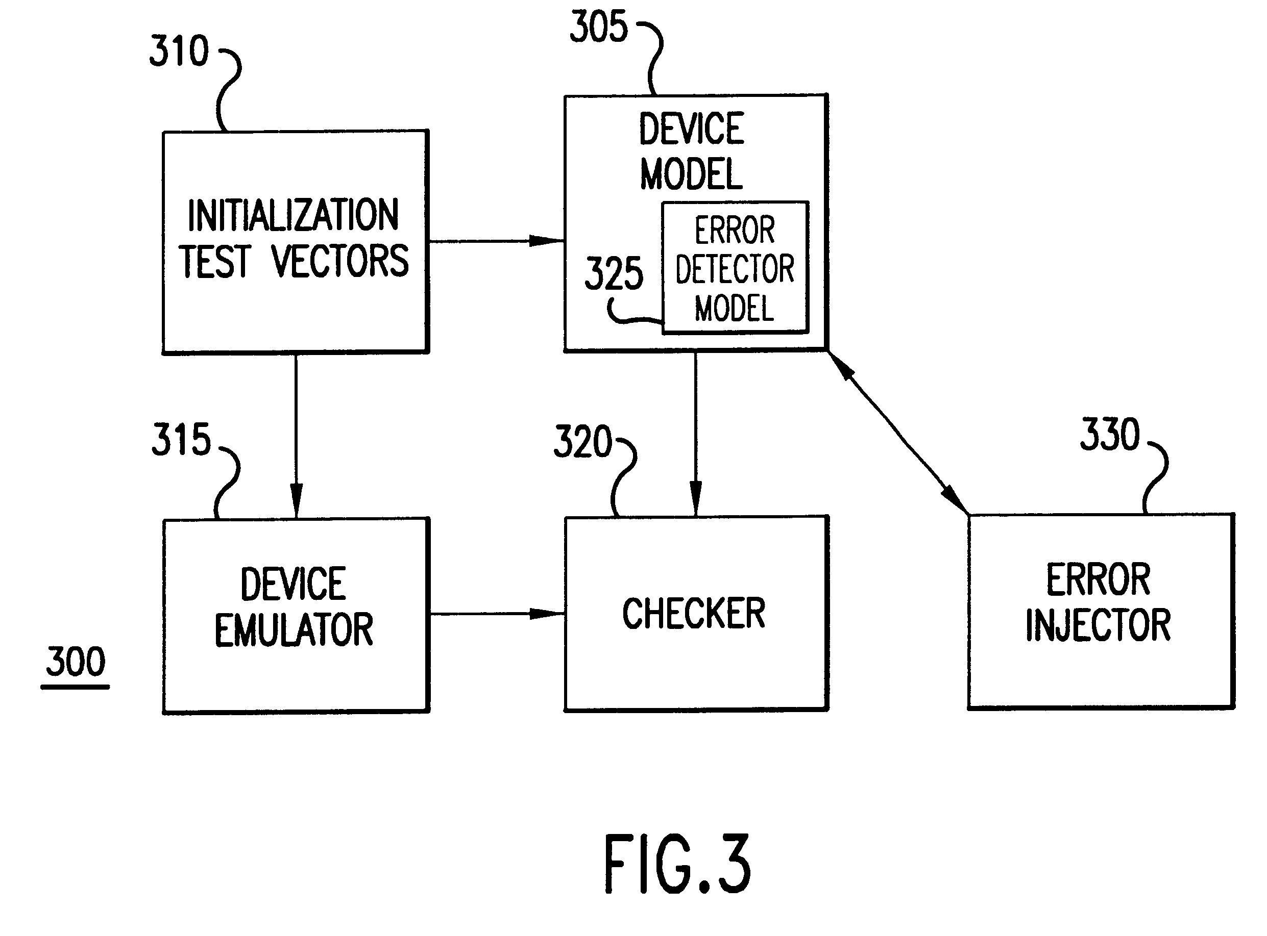
FIG. 3 is a block diagram of a testing arrangement 300 according to one embodiment of the present invention. FIG. 3 shows the testing arrangement 300 having an error injector 330 along with other elements similar or identical to those from the testing arrangement 200 (FIG. 2). The error injector 330 is a software module that connects to the device model 305. Typically, the error injector 330 runs in parallel (e.g., in the background or the foreground) with the simulated operation of the device model 305 and has shared access to the data structures that the device model 305 uses to simulate internal device operations. The error injector 330 monitors operation of the device model 305, waiting for a predetermined event or condition that triggers error injection. Upon detection of a triggering event or condition, the error injector 330 writes an error pattern into a particular part of the data structures that the device model 305 uses to simulate internal device operations. As a result,...


PUM


Abstract

Disclosed is a device and method for testing of a program or a design of an electronic device comprising digital logic circuitry. The method comprises testing the design of software or an electronic device and injecting, after initiation of the testing step, a predetermined error pattern into a value operated upon by the design of the digital logic circuitry. In a preferred embodiment, the software is a simulation of the design of a processor having a cache with error detection and/or correction circuitry. A triggering condition is preferably a cache hit, in response to which a detectable error is injected into the cache. The simulated operations of the model are observed to determine whether the injected error is detected, as should happen if the processor's error detection circuitry has been designed properly. In another respect, the invention is an apparatus, or computer software embedded on a computer readable medium, for testing a program comprising an error detector. The apparatus or software comprises the program, an error injector module connected to the program; and a checker module connected to the program. The checker module is capable of determining whether the program responds appropriately to an error dynamically produced by the error injector module during execution of the program. By injecting errors dynamically the invention easily facilitates precisely focused testing at any time during simulated operation regardless of initialization conditions.

Description

The invention relates to testing of error detection. More particularly, the invention relates to methods and equipment for testing error detection and / or correction in a program, such as a design simulation of a processor or a similar digital logic device.Whenever a new electronic device is designed, it is necessary to test the device to verify that it performs as intended. This is particularly true for electronic devices comprising digital logic circuitry. Because the number of digital logic variables can be large and because each variable can be in a number of states, the possible combinations and permutations of conditions for a digital logic circuit can be enormous. This is especially true for large, complex digital logic circuits, such as processors (including, for example, general purpose microprocessors, mathematical processors or coprocessors, digital signal processors, or other special purpose processors, controllers, microcontrollers, or microprocessors), which, accordingl...

Claims


Application Information

Patent Timeline
IPC IPC(8): G01R31/3183G01R31/28G06F11/267G11C29/02
CPCG01R31/3183G11C29/02G06F11/2215
Inventor WALKER, SHAWN KENNETH
Owner SAMSUNG ELECTRONICS CO LTD
Why Eureka
Try Eureka