Passive ball capture joint

a ball capture and ball joint technology, applied in the direction of packaging, manufacturing tools, couplings, etc., can solve the problems of low cost and very low strength in the axial direction of ball joints, joints are not generally considered useful as passive capture, and do not lend themselves

Inactive Publication Date: 2003-04-01
NASA
View PDF13 Cites 30 Cited by
  • Summary
  • Abstract
  • Description
  • Claims
  • Application Information

AI Technical Summary

Benefits of technology

Still another object of the present invention is to provide a passive ball capture joint having a mechanized structure for making the joint a rigid one.
A still further object of the present invention is to provide a passive ball capture joint that facilitates ejection of the captured ball once the joint has been unlocked.

Problems solved by technology

Such ball joints are characterized by low cost and very low strength in the axial direction as they are generally used to transmit forces in a plane normal to the installation axis.
Further, these joints are not generally considered useful as passive capture joints since they require more force to assemble than they can safely transmit in the axial direction.
However, there are many applications (e.g., space vehicle docking, underwater capture, etc.) that do not lend themselves to the above-described manual unlocking structure.

Method used


Image

  • Passive ball capture joint
  • Passive ball capture joint
  • Passive ball capture joint

Examples


Embodiment Construction

)

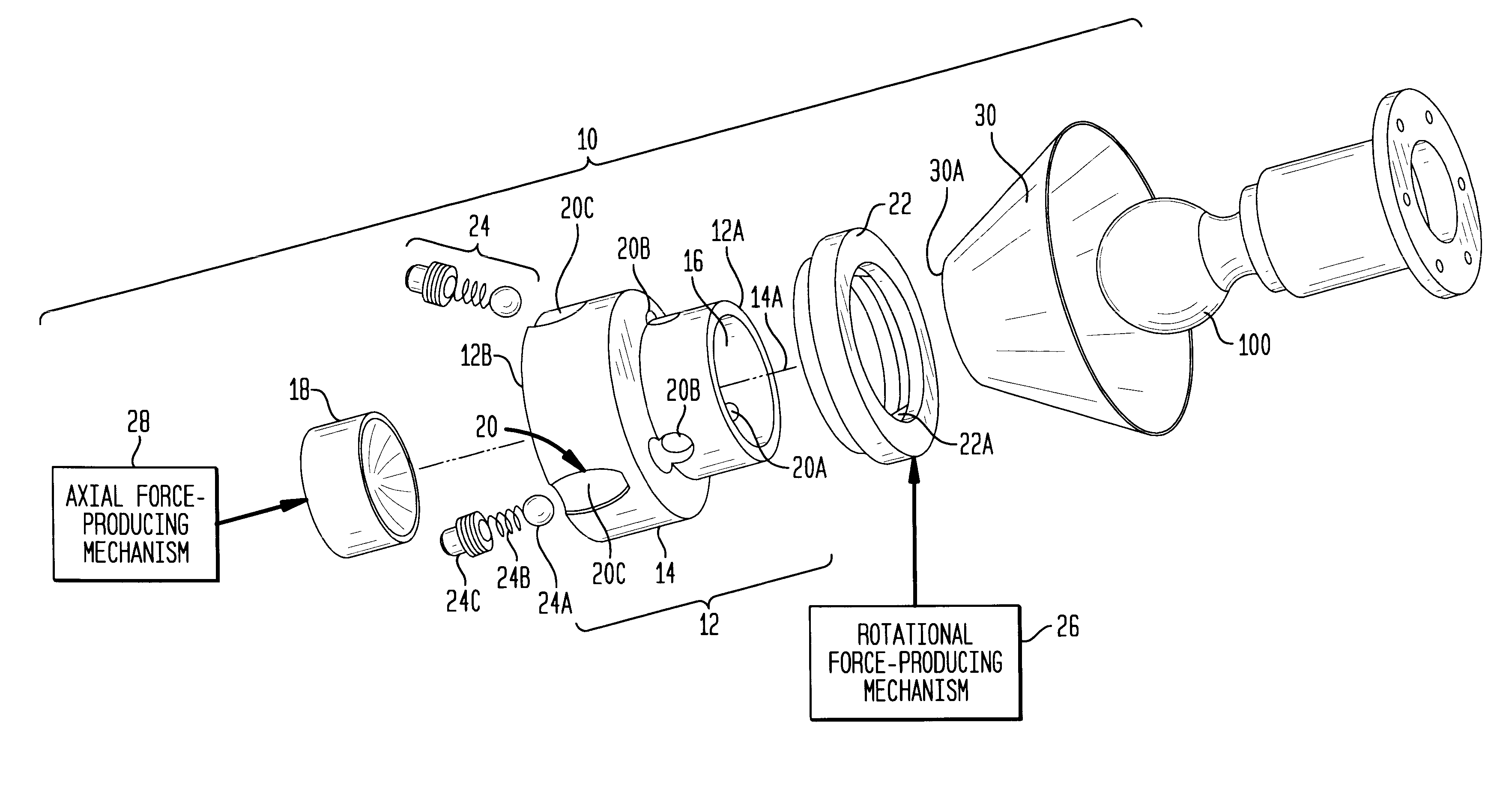
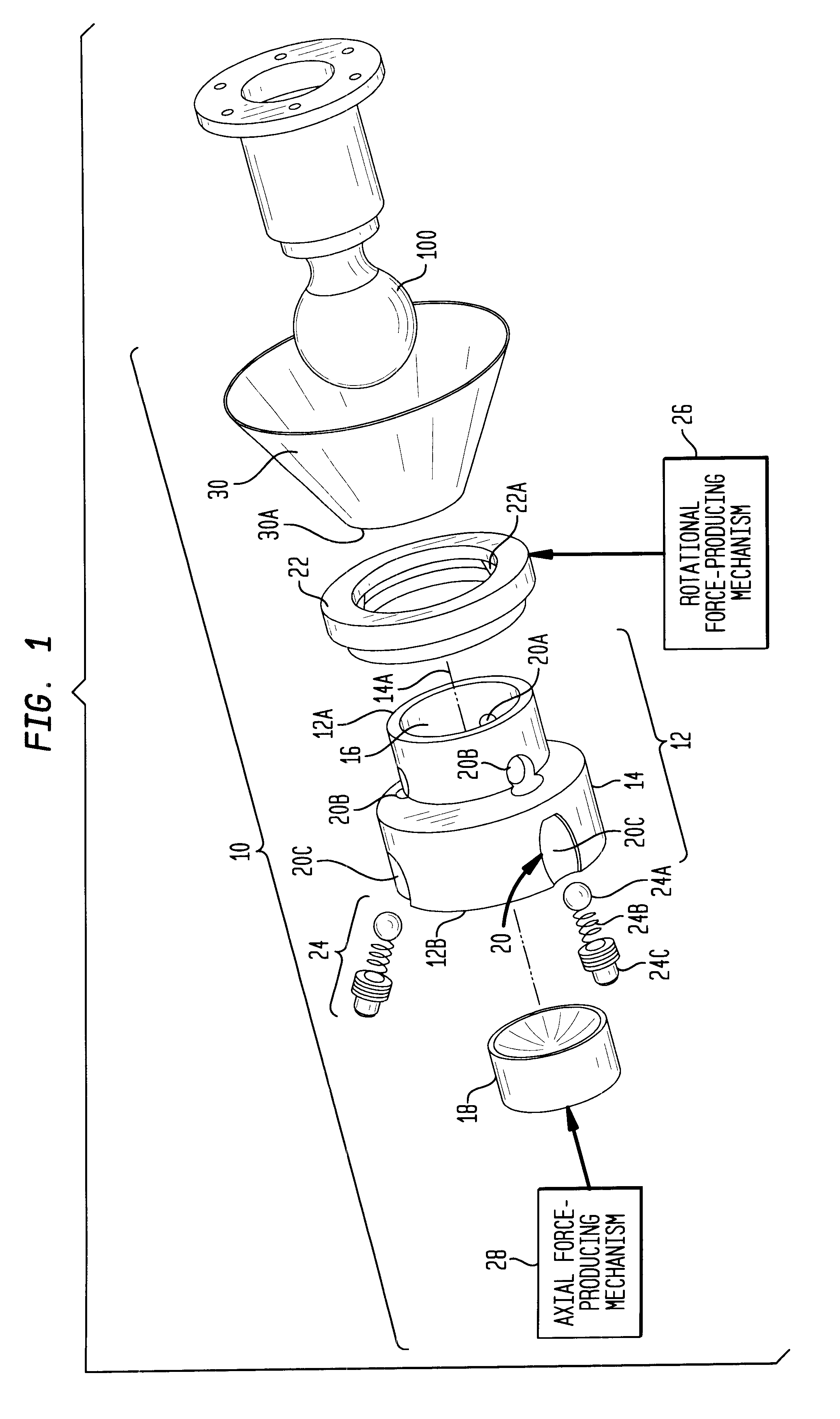
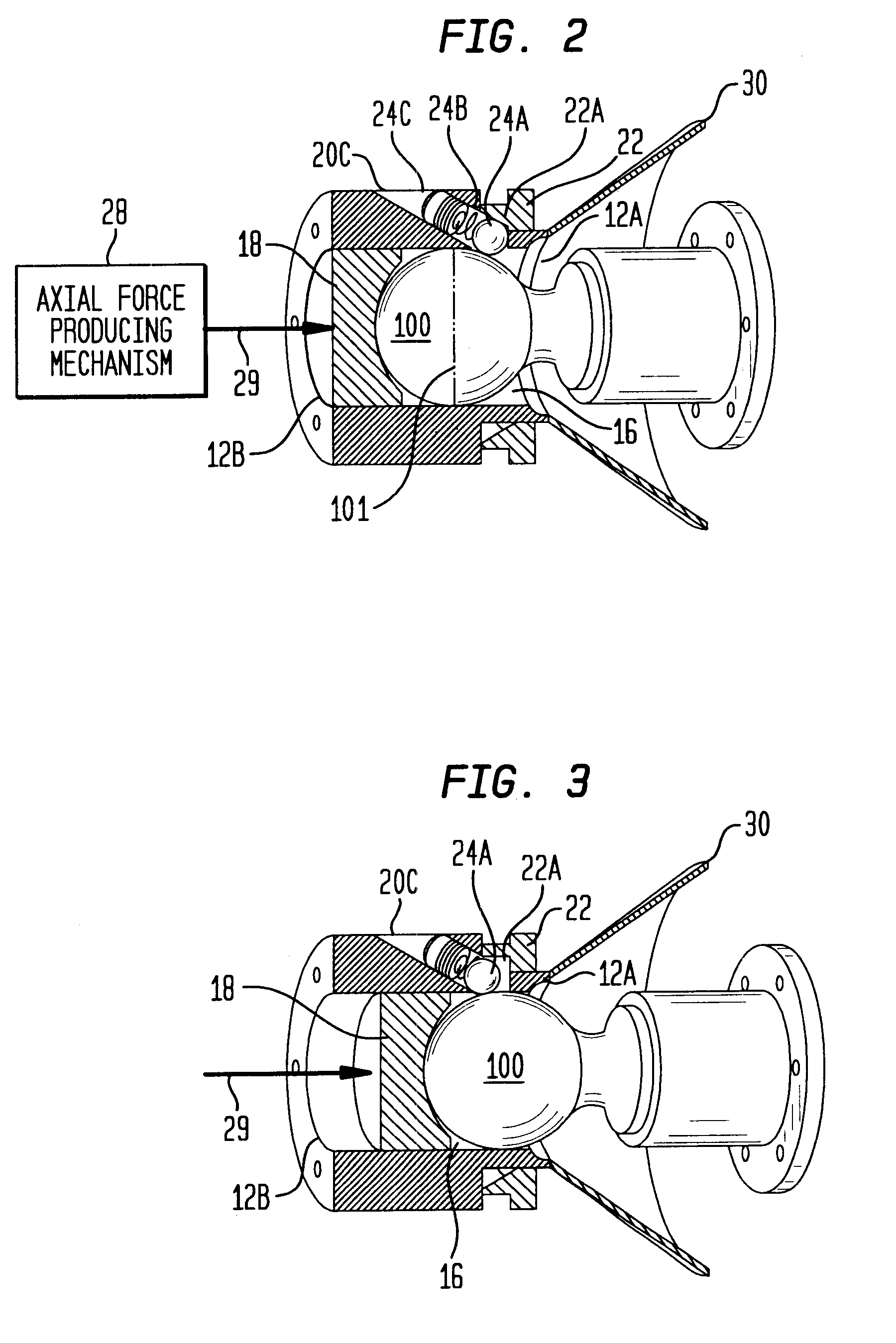
Referring now to the drawings, and more particularly to FIG. 1, an exploded view of a passive ball capture joint in accordance with the present invention is shown and referenced generally by reference numeral 10. Ball capture joint 10 is designed to passively capture and lock onto a joint ball 100, the particular design of which is not a limitation of the present invention. Further, ball capture joint 10 can be selectively unlocked and simultaneously eject joint ball 100.

In general, ball capture joint 10 includes a socket assembly, a lock / unlock ring coupled to the socket assembly, and a rigidizing / ejection assembly. More specifically, the socket assembly includes an open-ended sleeve 12 defined by a base 14 having an exterior wall forming a chamber 16 having an interior wall. Chamber 16 is sized to receive joint ball 100 therein via open end 12A of sleeve 12. A ball receiving load / eject cup 18 is sized to slide within chamber 16 via an axial force applied thereto at open end 12B a...


PUM


Abstract

A passive ball capture joint has a sleeve with a plurality of bores distributed about a circumference thereof and formed therethrough at an acute angle relative to the sleeve's longitudinal axis. A spring-loaded retainer is slidingly fitted in each bore and is biased such that, if allowed, will extend at least partially into the sleeve to retain a ball therein. A ring, rotatably mounted about the bores, has an interior wall defining a plurality of shaped races that bear against the spring-loaded retainers. A mechanized rotational force producer is coupled to the ring. The ring can be rotated from a first position (that presses the retainers into the sleeve to lock the ball in place) to a second position (that allows the retainers to spring back out of the sleeve to release the ball).

Description

1. Field of the InventionThis invention relates to ball capture joints. More specifically, the invention is a passive ball capture joint that can be positively and rigidly locked into position once capture has occurred and that includes an ejection mechanism when the joint is to be uncoupled.2. Description of the Related ArtA wide variety of "snap together" joint couplings are known in the art. Included in this class of joints are ball-type joints which are often used in automotive linkages. Such ball joints are characterized by low cost and very low strength in the axial direction as they are generally used to transmit forces in a plane normal to the installation axis. Further, these joints are not generally considered useful as passive capture joints since they require more force to assemble than they can safely transmit in the axial direction.A snap-fit ball joint design that can be used as a passive capture joint having three degrees of freedom is disclosed in U.S. Pat. No. 6,18...

Claims


Application Information

Patent Timeline
Patent Type & Authority Patents(United States)
IPC IPC(8): B60D1/00B60D1/06B60D1/28F16C11/06
CPCB60D1/06B60D1/065F16C11/069B60D1/28Y10T403/32631Y10T403/592
Inventor CLOYD, RICHARD A.BRYAN, THOMAS C.
Owner NASA
Why Eureka
Try Eureka