
Tool for chip removing machining

Inactive Publication Date: 2003-04-01
SANDVIK INTELLECTUAL PROPERTY AB
View PDF17 Cites 31 Cited by
  • Summary
  • Abstract
  • Description
  • Claims
  • Application Information

AI Technical Summary

Benefits of technology

The present invention aims at obviating the above-mentioned inconveniences of the prior art and at providing an improved tool of the type mentioned initially. Thus, a primary aim of the invention is to provide a tool, the cutting body of which may be corrected to an appurtenant shaft in an accurate and reliable way. Another aim of the invention is to create a tool, which enables assembly and disassembly of the cutting body in a fast and simple way while ensuring an exact centering or positional determination of the cutting body in relation to the shaft. It is also an aim to provide a tool, which is structurally simple and may be manufactured by means of conventional manufacturing methods.

Problems solved by technology

In modern machine tools, said shafts are so sophisticated and expensive that they cannot, for economical reasons, be integrated with the wearing part of the tool, viz. the cutting body, while forming a single tool which may be discarded when the cutting body has been consumed.
In other words, it is profitable to make the cutting body proper as a detachable unit, which may be replaced, while the expensive shaft may be used during a long period of time.
An aggravating disadvantage of this type of tool is, however, that cutting edges cannot be formed in the area of the front end of the hole formed in the cutting body, from which it follows that the cutting body may be formed only for milling (e.g. milling of T-grooves), but not for drilling.
However, in this known tool, the locking between the cutting body and the shaft is unreliable.
If a tool of this type is exposed to considerable cutting forces, there is, however, a risk of the cutting head coming loose from the shaft or displaced from a centered position thereon.

Method used


Image

  • Tool for chip removing machining
  • Tool for chip removing machining
  • Tool for chip removing machining

Examples


Embodiment Construction

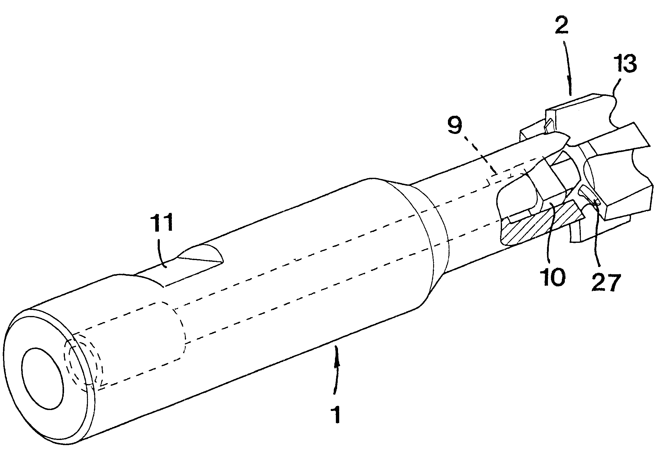
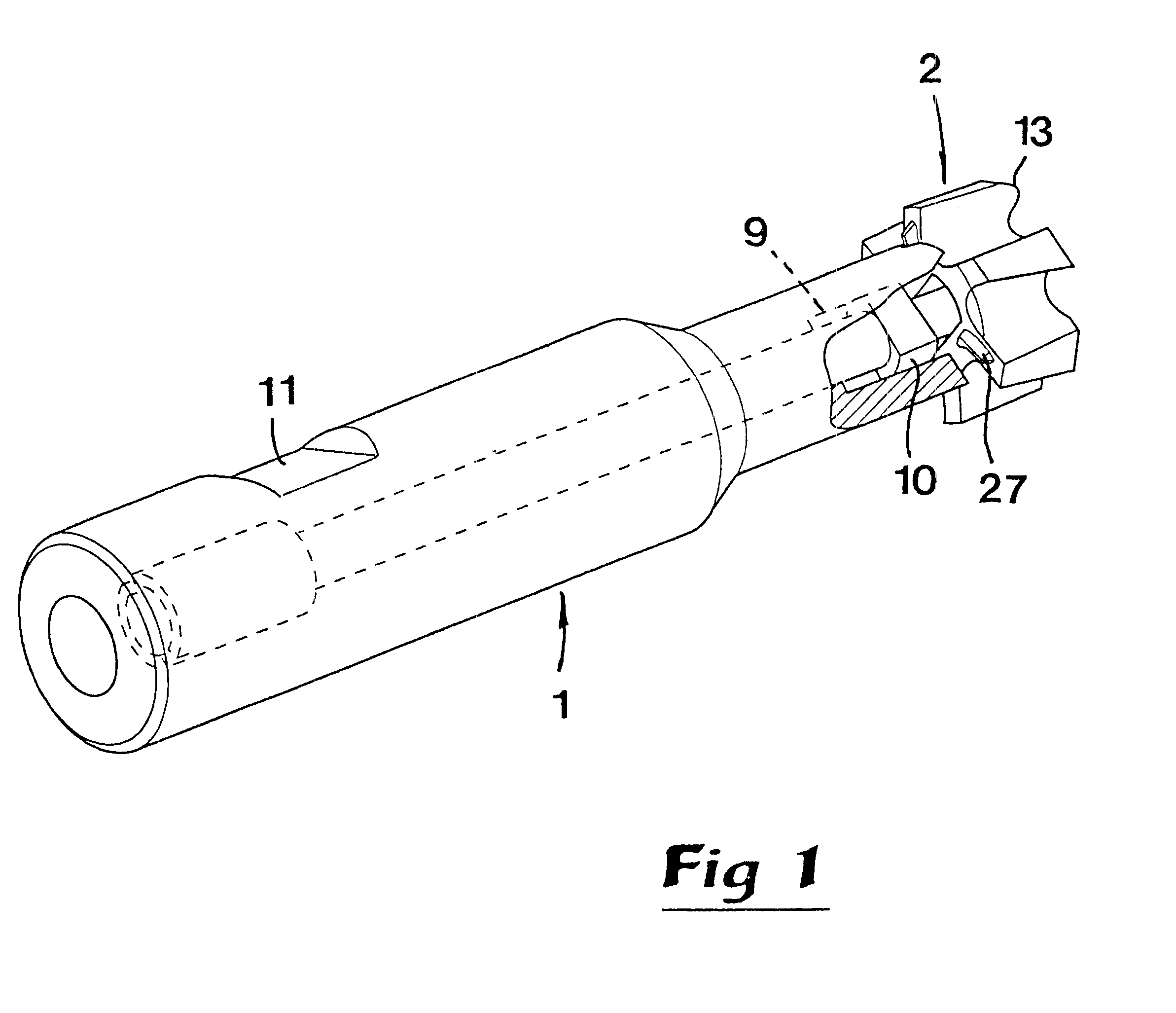
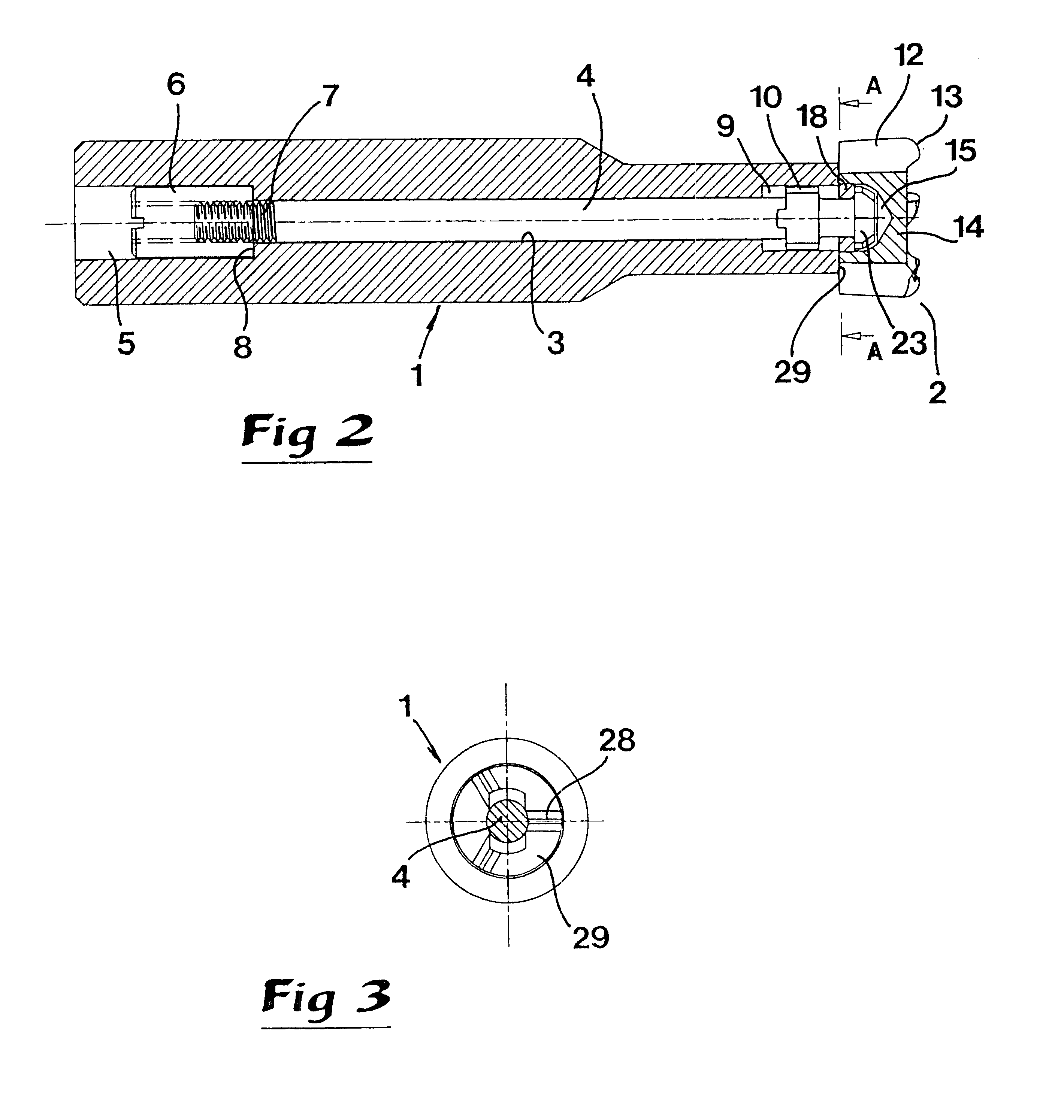
In FIGS. 1-10, a tool in the form of a shank-type cutter is illustrated, which includes a shaft I and a cutting body in the shape of a cutting head 2, which is detachably mounted on a front end of the shaft. Inside the shaft, an axial and central through bore 3 extends, which receives a drawbar 4. The bore 3 widens in a rear cylinder cavity 5, which houses an actuating element in the form of a nut 6, which with the female screw thereof is in engagement with a male screw 7 on the rear portion of the drawbar 4. At the transition section between the bore 3 and the wider cylinder cavity 5, there is a ring-shaped abutment surface 8 against which the front end of the nut 6 is pressed. At the front end of the shaft 1, adjacent to the bore 3, there is a number of axial grooves 9 in which chambers 10 on the drawbar 4 engage in order to make turning of the drawbar impossible relative to the shaft. In other words, the drawbar 4 is axially movable in relation to the shaft, but not turnable in r...


PUM

PropertyMeasurementUnit
Fractionaaaaaaaaaa
Angleaaaaaaaaaa
Fractionaaaaaaaaaa

Abstract

A rotatable tool for chip removing machining includes a shaft and a cutting body connected detachably to the shaft by a drawbar. At its front end the drawbar has a locking device for effecting mechanical engagement with the cutting body. The drawbar is axially movable by an actuating element located at a distance from the locking device. Inside the cutting body there is a cavity, which communicates with an opening in a rear part of the cutting body. The opening has a smaller width than the cavity, and the locking device has a larger width than the opening in order to be able to be pressed against an interior rear surface of the cavity of the cutting body after the locking device is inserted into in the cavity.

Description

This invention relates to a tool intended for chip removing machining the tool being of the type that comprises a shaft, which at a front end has a cutting body made of a hard material, which is connected detachably to the shaft by means of a drawbar arranged in a bore inside the shaft. The drawbar, at a front end thereof, has a locking device for mechanical engagement with the cutting body and which is movable axially between a protruded position and a retracted position by means of a tightening element located at a distance from the locking device.PRIOR ARTCutting tools of the type that makes use of a cutting body detachable from a shaft may, in practice, be in the form of milling cutters, in particular shank-type cutters, drills or thread cutters, the shaft usually having a long narrow, cylindrical shape. In modern machine tools, said shafts are so sophisticated and expensive that they cannot, for economical reasons, be integrated with the wearing part of the tool, viz. the cutti...

Claims


Application Information

Patent Timeline
IPC IPC(8): B23B27/16B23B31/10B23B31/113B23C5/10B23B51/00B23C5/02
CPCB23B27/164B23B31/113B23B51/00B23C5/10B23B2200/165Y10T407/245Y10T407/1908Y10T407/27Y10T407/192Y10T407/1922B23C2210/03
Inventor BEJERST.ANG.L, PERCARLSSON, SVEN-ERIK
Owner SANDVIK INTELLECTUAL PROPERTY AB
Learn More