Microfluidic device possessing structures enabling differential analysis of a single cell's constituents

Inactive Publication Date: 2020-08-06
KONINKLJIJKE PHILIPS NV +1
View PDF0 Cites 1 Cited by
  • Summary
  • Abstract
  • Description
  • Claims
  • Application Information

AI Technical Summary

Benefits of technology

[0091]The method does not require separate washing steps after the cell and/or the nucleus have been lysed for removing residual lysis buffer containing compound affecting or even impairing a subsequent analysis of constituents. This reduces time and chemicals required for analyzing cells, and thus costs. Thus, in alternative and/or additional embodiments, the method is performed without one or more washing steps after lysing the cell and/or without one or more washing steps after lysing the nucleus.
[0092]In addition, the method permits a much more accurate and reliable way of analysing single cell, in particular for correlating genomic information with transcriptome information. Since washing steps are not required, the likelihood of recovering all DNA molecules of a single cell increases significantly, because each additional step in the process of isolating DNA, especially washing steps, bear the risk of removing DNA from the sample. For instance, for single cell DNA

Problems solved by technology

However, it is very difficult establishing a direct link between cancer type, DNA mutations, and effective drug, because the DNA of tumor cells contain many mutations and it is difficult to assess which mutation drives the cancer, and which mutations are passerby mutations.
For cancer patients suffering from multiple tumors and/or tumors present at difficult to reach places, it may not be possible to obtain biopsies from the tumor(s) or all the tumors.
This drawback has led to the clinical development of assessing circulating tumor cell

Method used


Image

  • Microfluidic device possessing structures enabling differential analysis of a single cell's constituents
  • Microfluidic device possessing structures enabling differential analysis of a single cell's constituents
  • Microfluidic device possessing structures enabling differential analysis of a single cell's constituents

Examples


Embodiment Construction

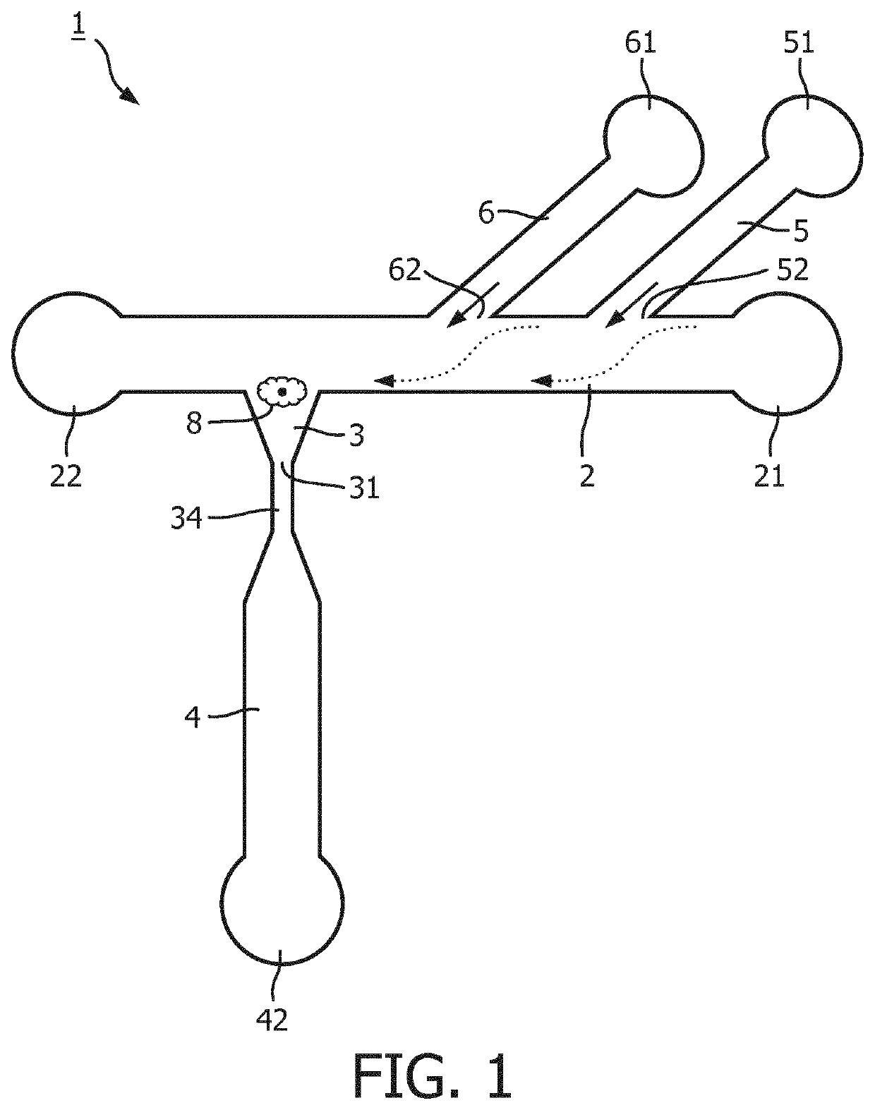
[0102]Referring to FIG. 1, a schematic illustration of an embodiment of a microfluidic structure in accordance with the invention is shown. The microfluidic structure 1 comprises a feeding channel 2 possessing an inlet (cell inlet) 21 and a waste outlet (22). The microfluidic structure 1 comprises a trapping structure 3 in fluid communication with and orthogonally extending from the flow path of the feeding channel 2. The trapping structure 3 comprises an outlet 31 in fluid connection with an output channel 4. The fluid connection 34 between the trapping structure 3 and the output channel 4 provides a narrow section configured to prevent a cell 8 being captured in the trapping structure 3 from accessing the output channel 4. The output channel 4 possesses an outlet 42 which is or may get fluid connection with an auxiliary chamber which is configured for detecting and / or analyzing one or more cell constituents. The microfluidic structure 1 further comprises two buffer channels, a fir...


PUM


Abstract

A method and a micro fluidic device comprising at least one micro fluidic structure for differential extraction of nuclear and extra-nuclear constituents of a single cell, said micro fluidic structure comprising a feeding channel for receiving a volume of a sample containing at least one cell, at least one trapping structure for capturing a single cell, and at least one output channel in fluid connection with the at least one trapping structure, wherein the at least one trapping structure extends from one side of the feeding channel substantially perpendicular to longitudinal axis of the feeding channel, the at least one trapping structure possessing an aperture at its end opposite to the fluid channel and in fluid communication with an output channel, said aperture being configured to provide a narrow section such that the nucleus of a cell captured in the trapping structure cannot pass through said narrow section into the output channel.

Description

FIELD OF THE INVENTION[0001]The invention relates to microfluidic devices for capturing and subsequently analyzing and / or characterizing single cells.BACKGROUND OF THE INVENTION[0002]The technology of nucleic acid sequencing rapidly developed to the level that sequencing is applied in the diagnosis of cancer. Typically, mutations in the DNA of a cancer patient are determined for assessing which type of treatment the patient has to undergo and which type of drug is to be administered. Indeed, some cases exist in which a direct link between mutations in the DNA of a cancerous tissue and the drug to be used for treating this type of cancer could have been established. For example, the HER2-neu gene leads to an overexpression of the HER2 receptor which stimulates cell division. In such cancers, administration of Herceptin offers an effective treatment. However, it is very difficult establishing a direct link between cancer type, DNA mutations, and effective drug, because the DNA of tumo...

Claims


Application Information

Patent Timeline
IPC IPC(8): B01L3/00C12M1/00
CPCB01L2300/0864B01L2400/0622C12M47/06B01L2200/0668B01L2300/0816B01L3/502761B01L2400/06C12N15/1003
Inventor VAN DER ZAAG, PIETER JANMARIE, RODOLPHE CHARLY WILLYVAN STRIJP, DIANNE ARNOLDINA MARGARETHA WILHELMINAOLESEN, TOMVULDERS, ROLAND CORNELIS MARTINUSKRISTENSEN, ANDERS
Owner KONINKLJIJKE PHILIPS NV
Why Eureka
Try Eureka