Locking mechanism for securely preventing disconnection between a plug and a receptacle

a locking mechanism and plug technology, applied in the direction of coupling contact members, coupling device connections, securing/insulating coupling contact members, etc., can solve the problems of deterioration of the locking mechanism as a result of repeated insertion of the plug connector into the receptacle connector, low locking mechanism, and inability to provide large force for holding the contacts in the housing

Inactive Publication Date: 2003-04-01
JAPAN AVIATION ELECTRONICS IND LTD
View PDF12 Cites 29 Cited by
  • Summary
  • Abstract
  • Description
  • Claims
  • Application Information

AI Technical Summary

Benefits of technology

It is therefore an object of the present invention to provide an electrical connector which has a lo...

Problems solved by technology

Since the contacts are normally made of material such as metal that is hard to be worn against the rubbing, the deterioration of the locking mechanism as a result of repeated insertion of the plug connector into the receptacle connector is extremely low.
However, the locking mechanism has the following problems.
When the connector is small and thin and has densely-arranged contacts, a mechanism for holding the contacts in a housing is complex so that it is impossible to provide large force for holding the contacts in the ...

Method used


Image

  • Locking mechanism for securely preventing disconnection between a plug and a receptacle
  • Locking mechanism for securely preventing disconnection between a plug and a receptacle
  • Locking mechanism for securely preventing disconnection between a plug and a receptacle

Examples


first embodiment

With reference to FIGS. 1 through 9, description will be made as regards an electrical connector according to the present invention.

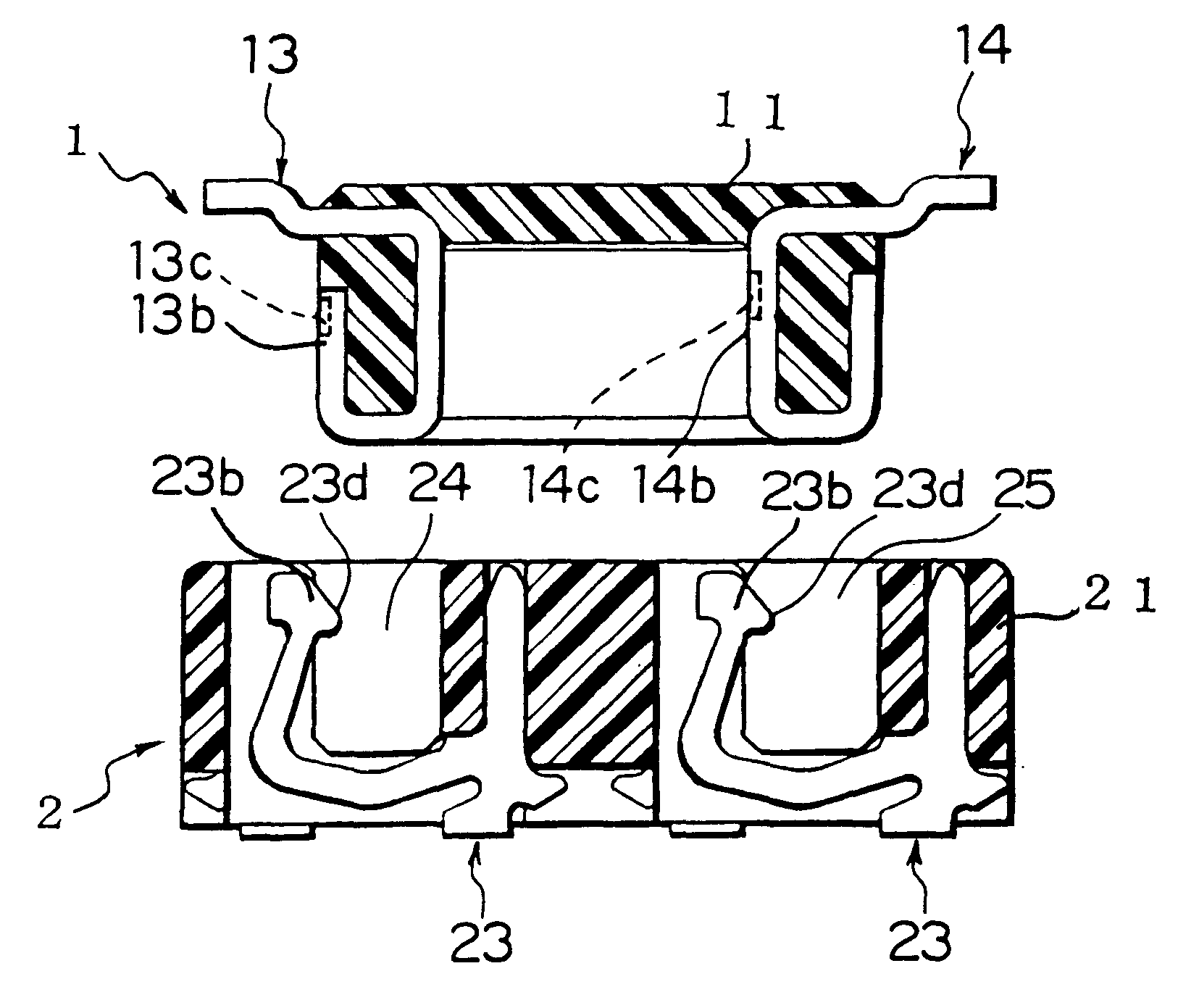
The electrical connector includes a plug connector 1 and a receptacle connector 2 which are connected to or disconnected from each other in a first direction. The following description will be made assuming that the plug connector 1 and the receptacle connector 2 are arranged on a circuit board, but it should be understood that the present invention is not limited thereto.

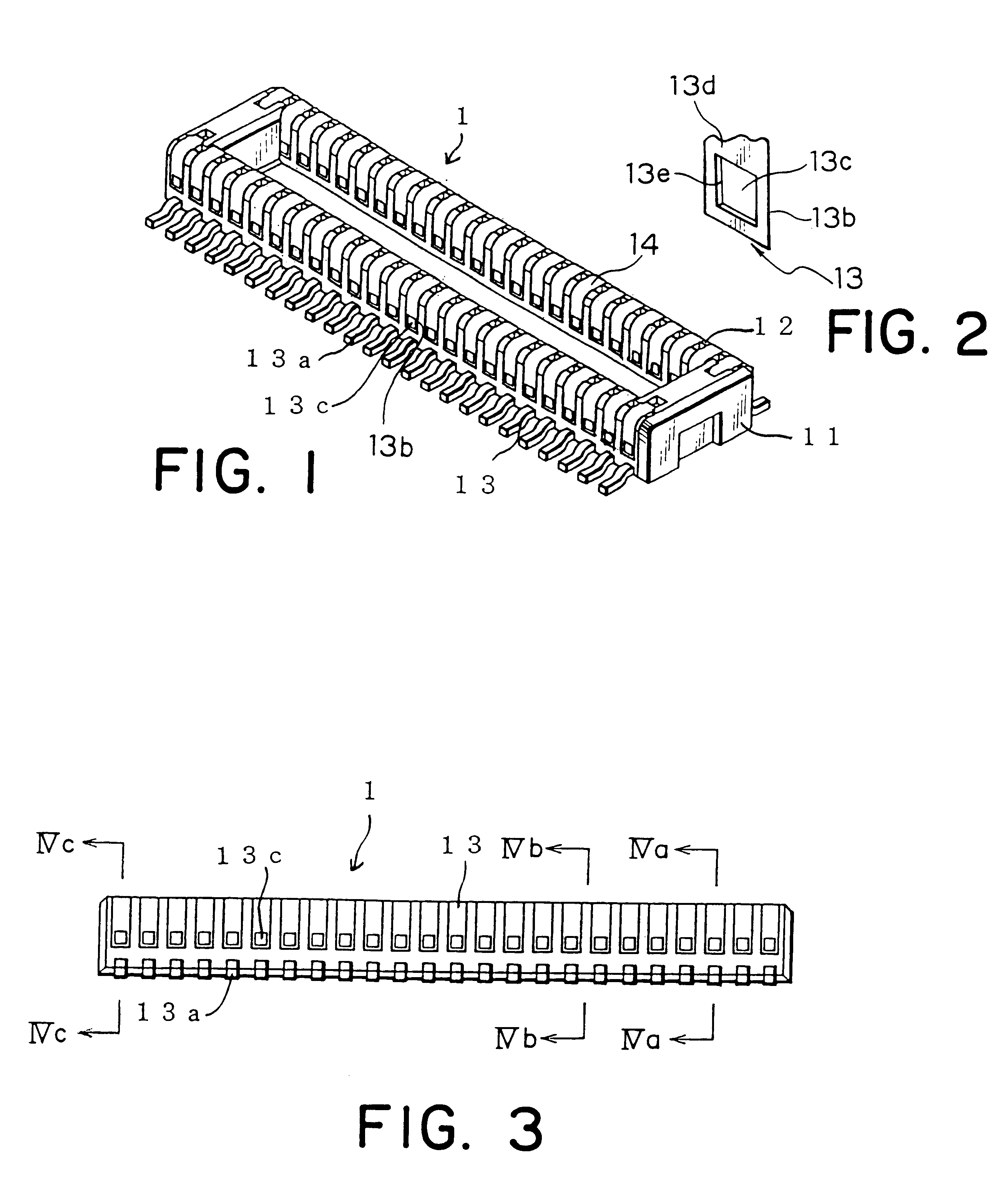
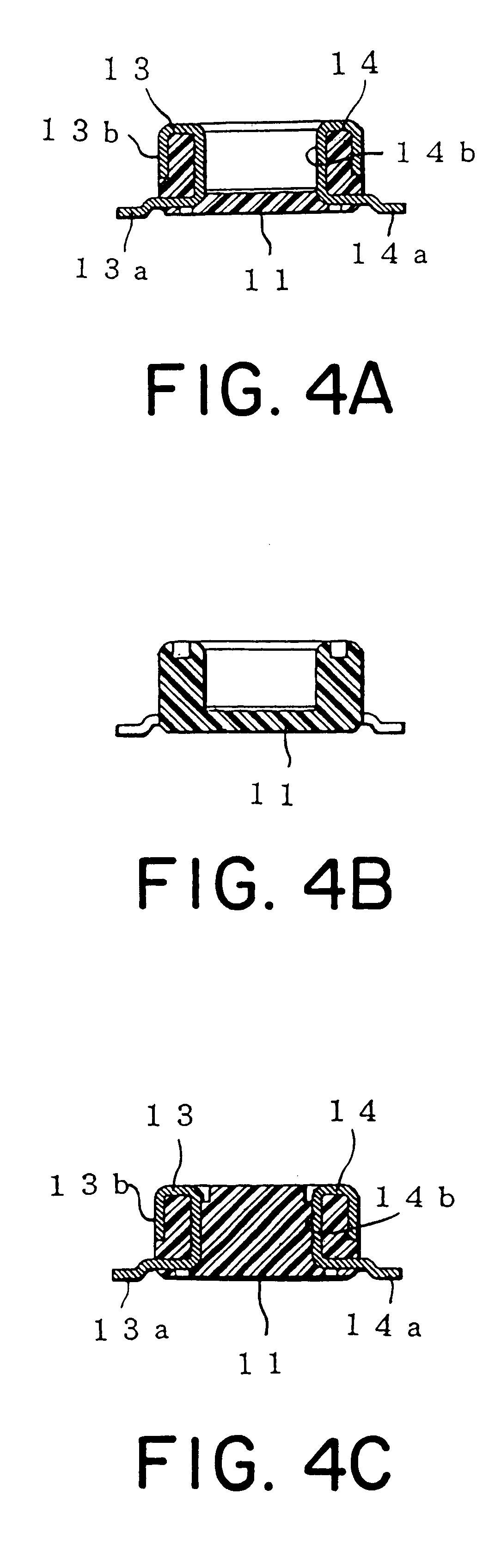
Referring to FIG. 1 through FIG. 4C, the plug connector 1 includes a plug housing 11 made of an insulating material such as synthetic resin and a plurality of plug contacts 13 and 14 parts of which are fixed and held in a plurality of parallel grooves 12 formed in the housing 11. The contacts 13 are aligned in parallel on the left side of the housing 11 in FIGS. 4A-4C. The contacts 14 are aligned in parallel on the right side of the housing 11 in FIG. 1.

Each of the contacts 13 has a bo...

second embodiment

With reference to FIGS. 11 through 13C, the description will be made as regards an electrical connector according to the present invention.

The electrical connector includes a plug connector 4. The plug connector 4 includes a housing 41 made of an insulating material such as synthetic resin and a plurality of contacts 43 which are fixed and held by contact holding portions 42 disposed on the both sides of the housing 41 and are aligned in parallel. The contacts 43 are aligned on the right and left contact holding portions 42 alternately i.e. in a zigzag configuration.

Each of the contacts 43 has a board connecting portion 43a connected by soldering or the like to an electrical circuit on the circuit board (not shown) on which the plug connector 4 is arranged and a contact portion 43b which comes in contact with a corresponding contact of a receptacle connector (not shown) when the plug connector 4 is connected to the receptacle connector. The contact portions 43b have flat surfaces ea...


PUM


Abstract

In a plug connector (1) for being connected to a receptacle connector (2) in a first direction, a plug contact (13) is held by a plug housing (11) and has a principal surface extending along the first direction. The plug contact is formed with a concave portion recessed from the principal surface in a second direction perpendicular to the first direction. A wall is remained between the principal surface and the concave portion. In the receptacle connector (2), a receptacle housing (21) holds a receptacle contact (23) for coming in contact with the plug contact in the second direction. The receptacle contact is formed with a projection (23d) which is positioned inside the concave portion when the plug connector is connected to the receptacle connector.

Description

BACKGROUND OF THE INVENTIONThe present invention relates to an electrical connector and, more particularly, to an electrical connector for electrically connecting printed circuit boards or the like.An electrical connector is used for electrically connecting printed circuit boards or electrically connecting a printed circuit board and an electrical cable such as a flexible printed circuit (hereinafter referred to as "FPC"). Such an electrical connector normally includes a plug connector and a receptacle connector to be connected to the plug connector.To prevent disconnection between the plug connector and the receptacle connector, for example, disclosed in Japanese Patent No. 2676063 is a locking mechanism for engaging contacts of the plug connector with contacts of the receptacle connector. Since the contacts are normally made of material such as metal that is hard to be worn against the rubbing, the deterioration of the locking mechanism as a result of repeated insertion of the plu...

Claims


Application Information

Patent Timeline
IPC IPC(8): H01R13/24H01R13/02H01R13/20H01R13/22H01R13/40H01R13/405H01R13/64H01R24/00H01R43/24H01R107/00
CPCH01R13/20H01R13/405H01R12/716H01R13/64
Inventor MASUMOTO, TOSHIO
Owner JAPAN AVIATION ELECTRONICS IND LTD
Why Eureka
Try Eureka