Power interruption detection

a technology of power interruption and detection device, applied in the direction of electric controller, ignition automatic control, instruments, etc., can solve the problem of impracticality of designing a redundant power supply system based on a battery

Inactive Publication Date: 2003-04-08
IBM CORP
View PDF15 Cites 28 Cited by
  • Summary
  • Abstract
  • Description
  • Claims
  • Application Information

AI Technical Summary

Problems solved by technology

However, in certain applications, it is impractical to design a redundant power supply

Method used


Image

  • Power interruption detection
  • Power interruption detection
  • Power interruption detection

Examples


Embodiment Construction

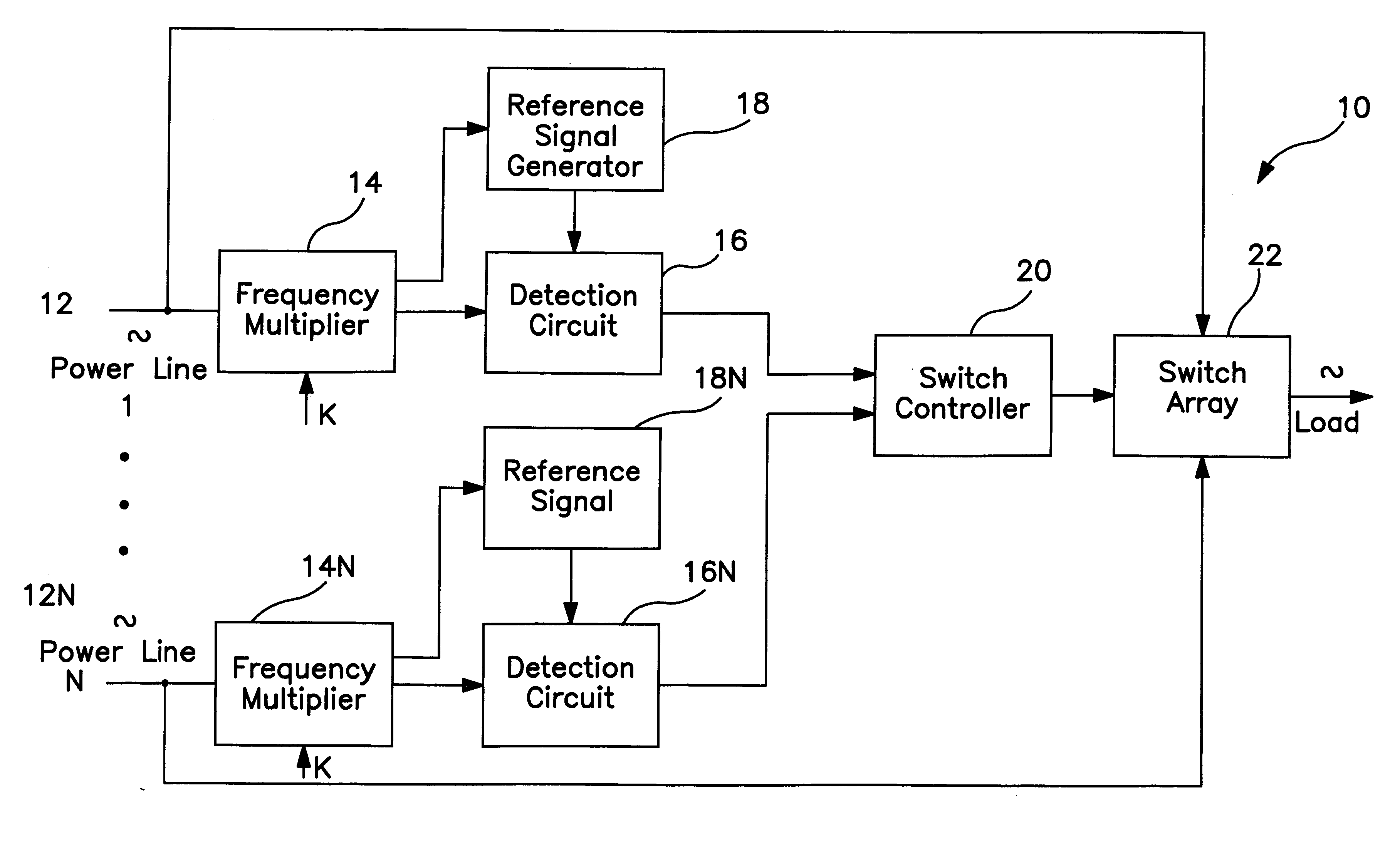
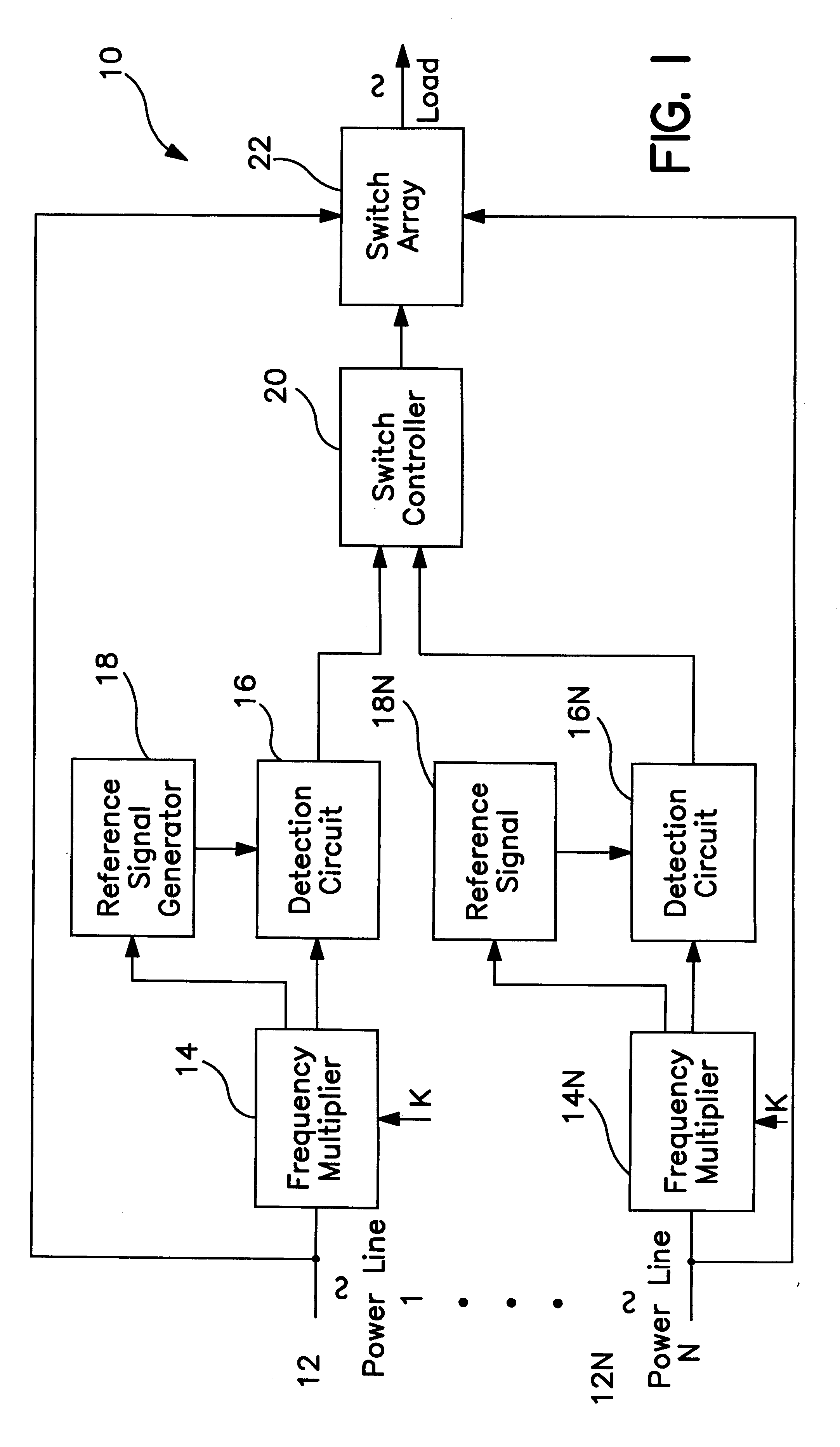
FIG. 1 depicts a block diagram of an example of a power interruption detection system 10 of the present invention. The system 10 is designed to detect the presence of a signal on an available power line 12 . . . 12n, and if a failure occurs on a particular power line, instruct a switch array to switch to another, viable power line, in a minimal time period. It should be noted that the present invention is intended to provide redundant switching between 2 or more available power sources. Thus, the circuitry 10 described herein may be duplicated for each source, as shown in FIG. 1 represented by an additional source line 12n and power interruption detection system 10, and as will become apparent in the following description.

The system 10 of FIG. 1 includes a frequency multiplier 14 coupled to a power line 12. In this example, power line 12 is an AC power source having a fixed frequency (e.g., 120 VAC at 50, 60 Hz.). The frequency multiplier multiplies the frequency of the input source...


PUM


Abstract

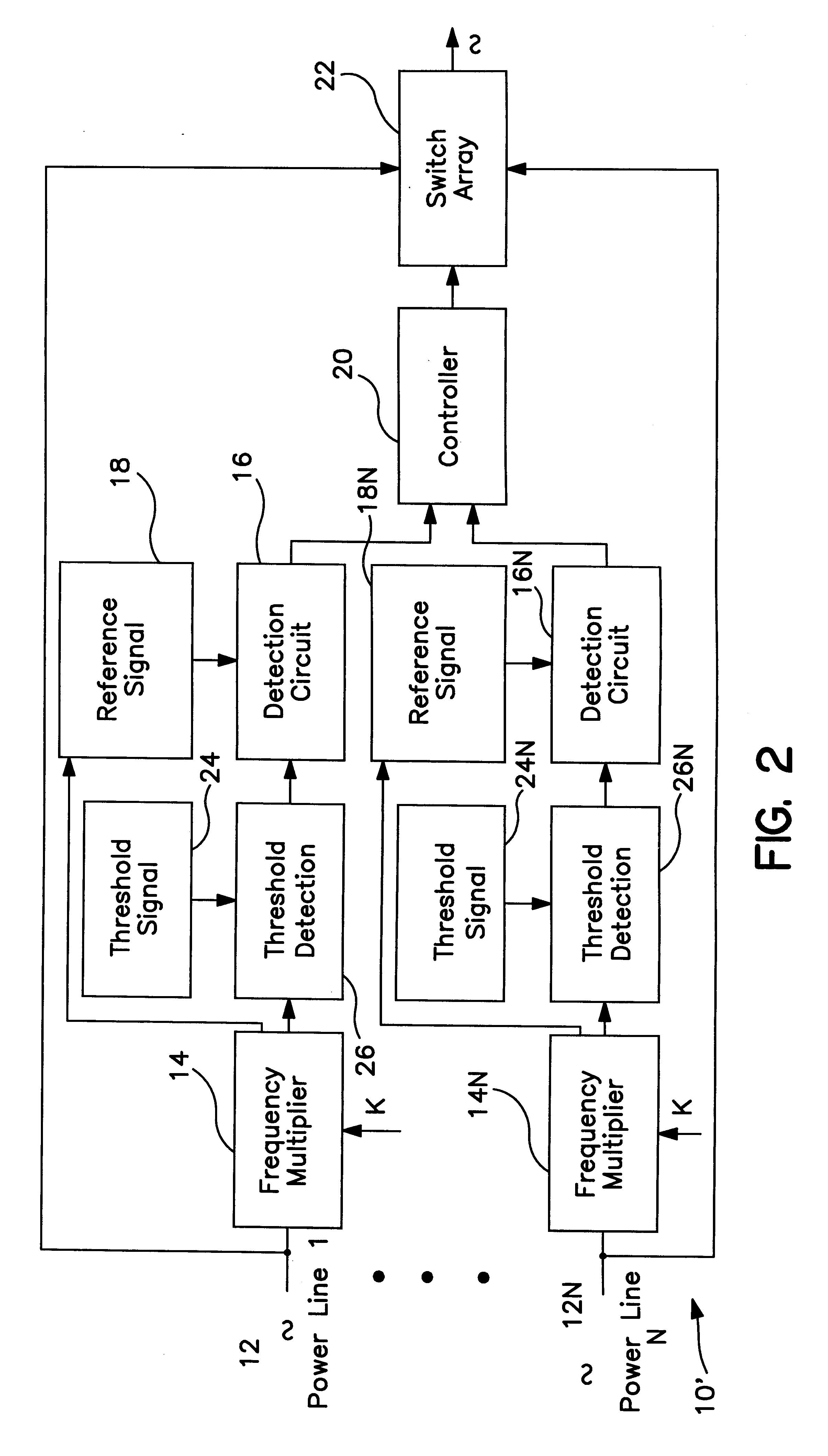
An AC power interruption detection system is provided which compares an AC signal with a phased AC reference signal to determine the presence or absence of an AC power signal. By comparing the AC power signal with a phased reference signal, power interruption detection occurs within a predetermined minimum time frame, for example, with ½ cycle. In exemplary embodiments, the detection system includes AC power signal frequency multiplying circuitry to improve speed and performance. In other exemplary embodiments, the detection system includes threshold detection circuitry to detect undervoltage (e.g., brownout) and/or overvoltage (e.g., spike) conditions of the AC power. In system-level embodiments, the interruption detection system is implemented in a switch array environment in which a switch controller controls a redundant switch array based on the detection signal generated by the power interruption detection system to couple a selected AC power line, from one or more redundant AC power lines available, to a load.

Description

1. Field of the InventionThe present invention relates to a system and methodology for providing high- speed detection of faults in an AC power line by using phase-locking techniques to detect a power interruption or power degradation within a predetermined minimum time period.2. Description of Related ArtNumerous power management systems exist which monitor an AC power line, and upon failure of the AC power, couple a battery backup system to a load. For example, U.S. Pat. No. 4,916,329 issued to Dang et al. discloses an uninterruptible power supply which monitors variations in a single AC power supply and decides, based on certain threshold limitations, whether to couple a backup battery supply to a load. Similar examples can be found in U.S. Pat. Nos. 5,790,391; 5,670,833; 5,602,462; and 4,916,329.However, in certain applications, it is impractical to design a redundant power supply system based on a battery backup system since some loads will quickly deplete a battery. Such imple...

Claims


Application Information

Patent Timeline
IPC IPC(8): H02J9/06
CPCH02J9/06
Inventor EMBERTY, ROBERT GEORGEHEW, ERIC Y. K.KLEIN, CRAIG ANTHONY
Owner IBM CORP
Why Eureka
Try Eureka