Radar system having simultaneous monostatic and bistatic mode of operation

a radar system and monostatic technology, applied in the field of pulse doppler radar, can solve the problems of insufficient accuracy of target's cross-range (also known as its azimuthal position or sometimes, doppler direction), and even more exaggeration of azimuthal positional uncertainty,

Inactive Publication Date: 2003-04-08
THE BOEING CO
View PDF5 Cites 43 Cited by
  • Summary
  • Abstract
  • Description
  • Claims
  • Application Information

AI Technical Summary

Problems solved by technology

However, the target's cross-range (also known as its azimuthal position or sometimes, doppler direction) is much less accurate.
Further, this azimuthal positional uncertainty is even more exaggerated for space based radar.
However, the azimuthal position uncertainty for space based radar may be on the order of hundreds of meters and even a few kilometers.
However, it is well known that difficulties arise even using two radar sensors.
It is especially difficult to locate and track one target when the target density of moving targets in an area being surveilled exceeds or becomes comparable to the major axis dimension (azimuthal dimension) of a single sensor error ellipse.
When this occurs, multiple targets occur at nearly the same range from each sensor, causing target error ellipses from one sensor to overlap target error ellipses from the other sensor at multiple locations.
This makes accurately locating and tracking targets much more difficult.
This second type of overlap can result in a false target or a "ghost" and is typically referred to as a multi-lateration problem.
It is difficult to discriminate between a true targets and ghosts under these conditions.
These large cross range positional errors are vexations to current radar systems as well as multi-target indication surveillance systems currently being developed, whether they are intended as airborne or spaceborne radar systems.
Unfortunately, with cross range errors that may be as much as tens or hundreds of meters or even kilometers, even using bistatic radar this tracking capability is not generally possible, especially where the target of interest is near other moving objects, e.g., a truck on a busy road.
This precision is not available with current state-of-the-art airborne target surveillance radars, much less for spaceborne moving target surveillance radars.

Method used


Image

  • Radar system having simultaneous monostatic and bistatic mode of operation
  • Radar system having simultaneous monostatic and bistatic mode of operation
  • Radar system having simultaneous monostatic and bistatic mode of operation

Examples


Embodiment Construction

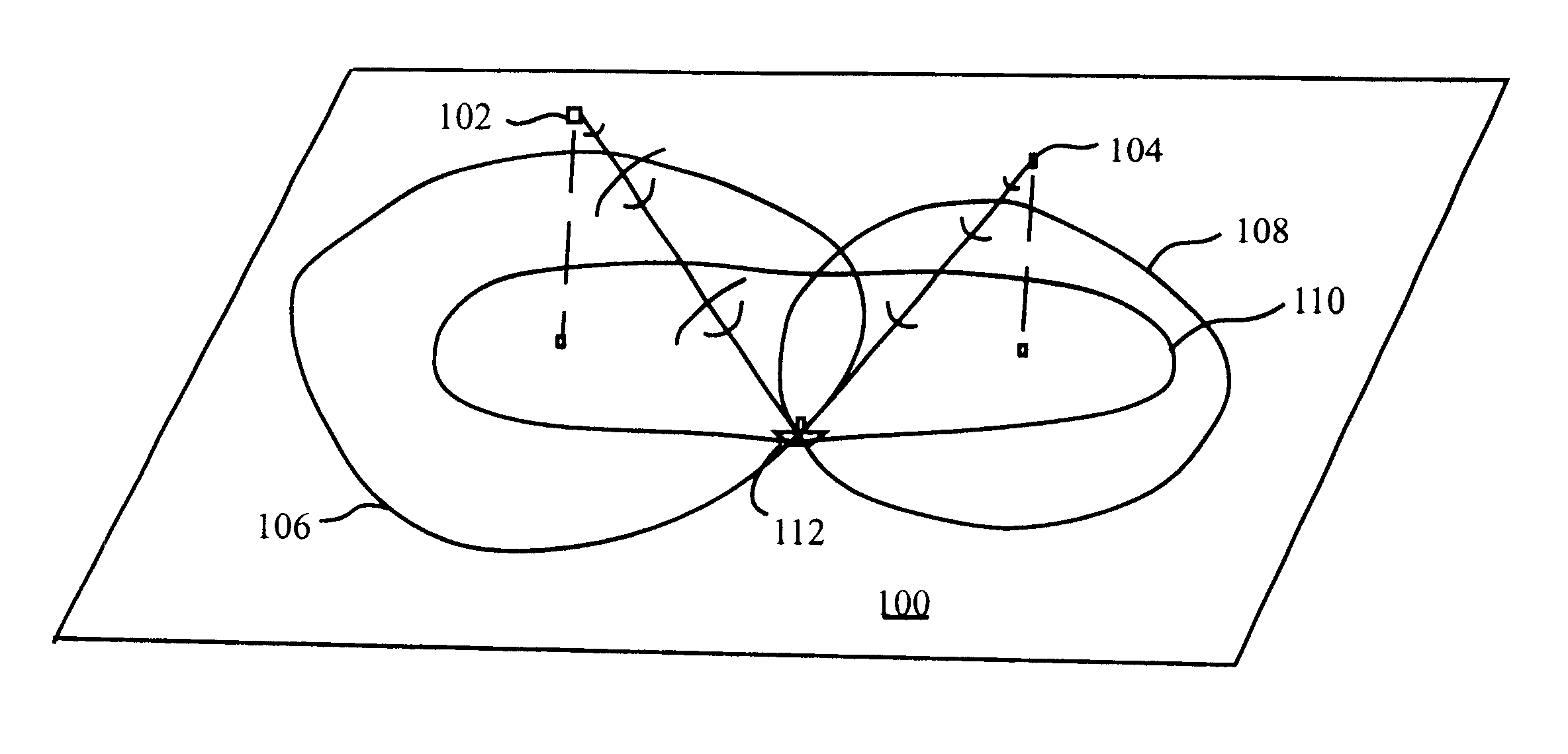
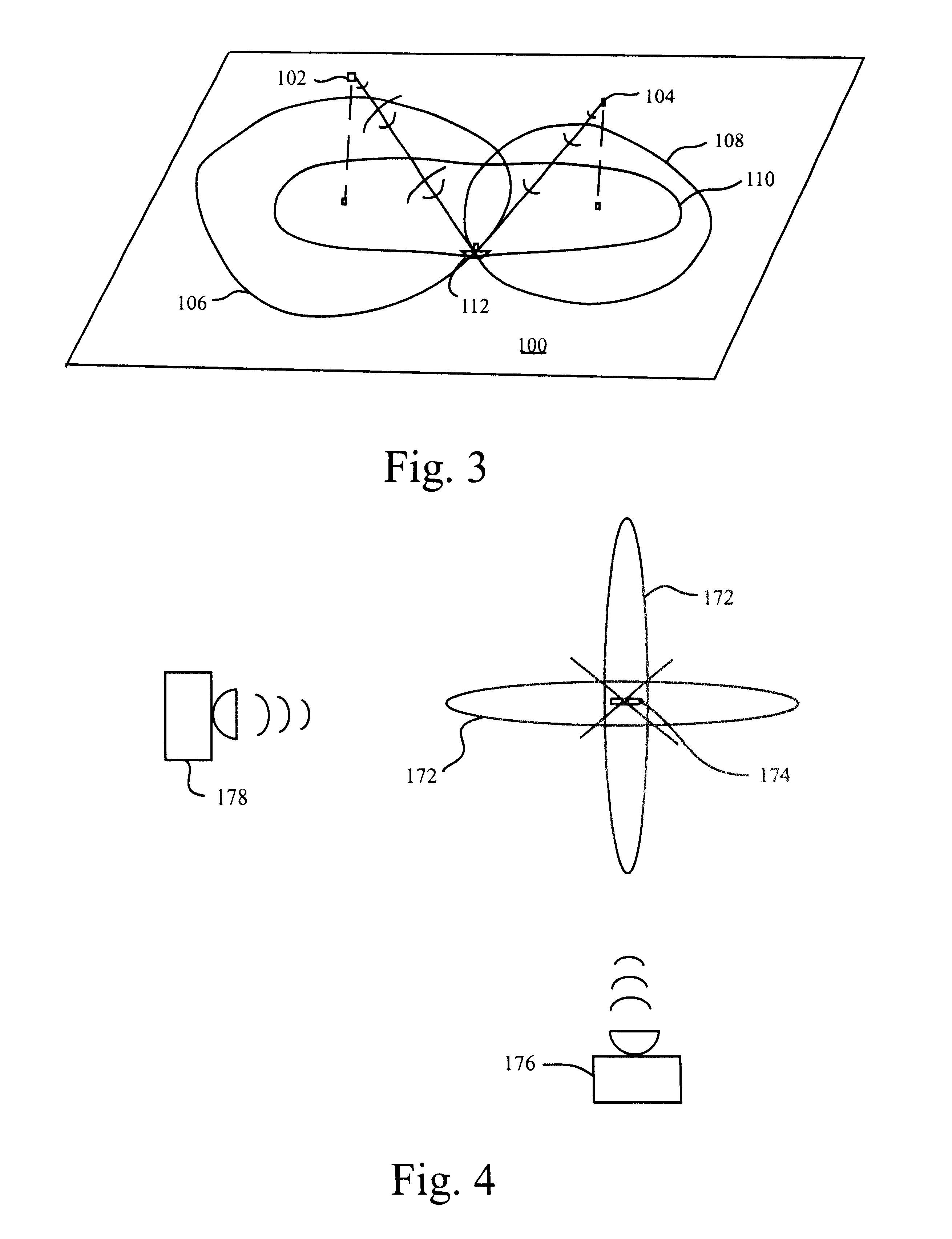
In a first preferred embodiment, two independent airborne or spaceborne radar sensors operate monostatically and bistatically, simultaneously, to surveil for moving targets that are constrained to travel on the ground and for known sensor locations and altitudes with respect to the ground. In a second preferred embodiment, two independent sensors (ground-based, airborne, or spaceborne) surveil for moving targets that are not constrained to travel over a known surface position such as the ground and, wherein the moving targets may be airborne or spaceborne.

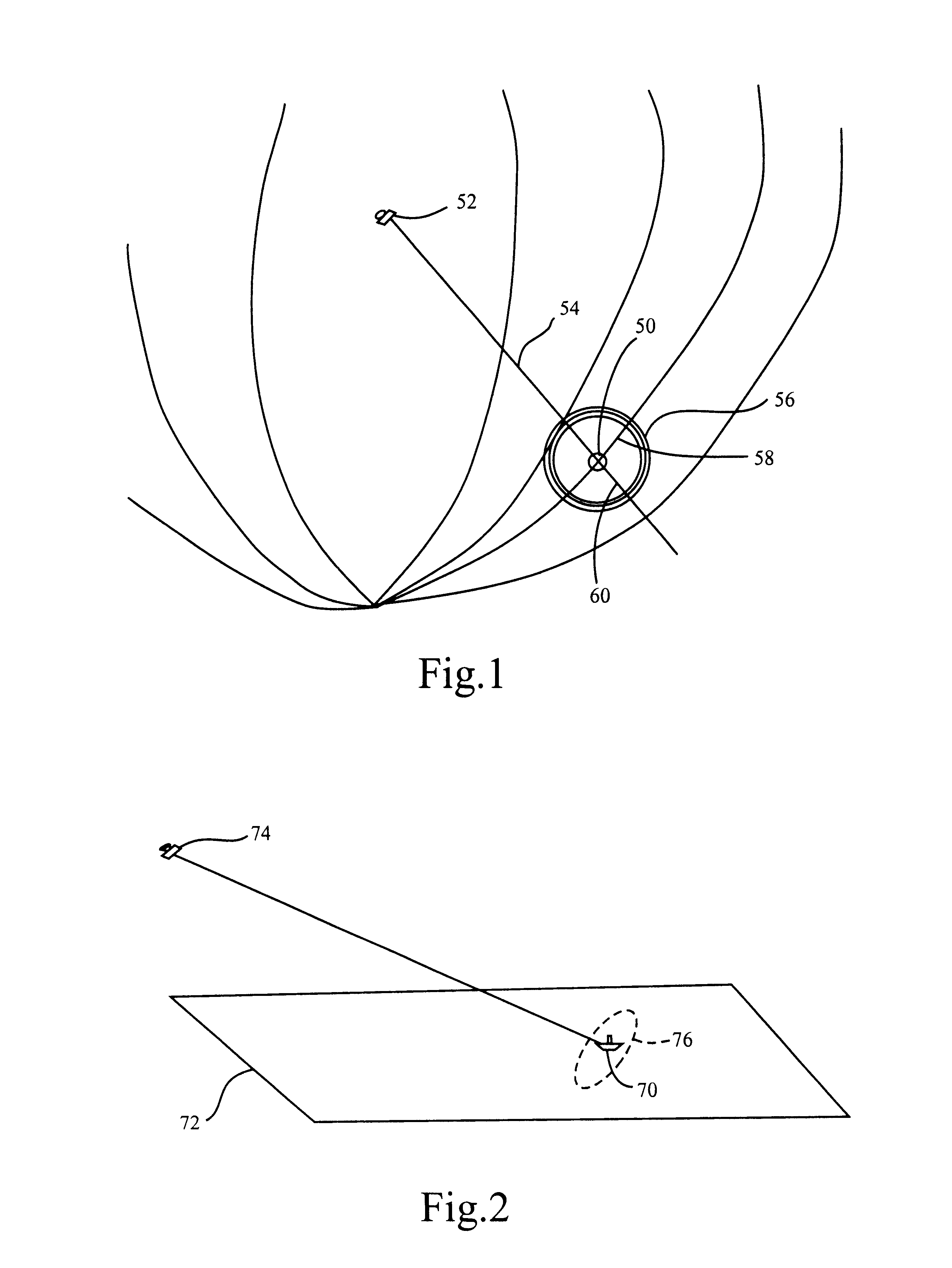
FIG. 1 shows a basic example of geometry in locating objects detected by a single pulse doppler radar. In this example, a target 50 is detected by a single radar sensor 52. The most accurately determinable target's position coordinate is the target's range from the sensor 52 represented by ray 54. For a particular range 54, the target 50 may be treated as lying within a spherical shell 56. The thickness of the shell 56 is equal to ...


PUM


Abstract

A pulse doppler radar system simultaneously operating monostatically and bistatically. A pair of radar unit operate monostatically transmitting a radio frequency (RF) energy signal and receiving a RF return from the RF energy signal. In addition, simultaneously, one unit operates as a receiver receiving a bistatic return from the other. Information from the bistatic return is combined with information from monostatic returns to locate individual targets.

Description

1. Field of the InventionThe present invention is related to pulse doppler radar for detecting, precisely locating and tracking moving objects including airborne and spaceborne objects and, more particularly, to airborne or spaceborne pulse doppler radar for detecting, precisely locating and tracking moving objects on the ground.2. Background DescriptionA monostatic radar system has its transmitter and receiver at the same location. A bistatic radar has a transmitter at one location and a receiver at a different, most often, distant location. Regardless of whether a radar system is monostatic or bistatic, when a target is detected using a single radar sensor, the target's positional range (distance from the sensor) is highly accurate. However, the target's cross-range (also known as its azimuthal position or sometimes, doppler direction) is much less accurate. Thus, a target's distance is always known to a much greater degree of certainty than the target's actual position. Coarser, ...

Claims


Application Information

Patent Timeline
Patent Type & Authority Patents(United States)
IPC IPC(8): G01S13/87G01S13/00
CPCG01S13/878G01S13/003
Inventor JENSEN, ERIC B.
Owner THE BOEING CO
Why Eureka
Try Eureka