Jet engine nozzle with variable thrust vectoring and exhaust area

a technology of jet engine and nozzle, which is applied in the direction of vessel construction, marine propulsion, aircraft navigation control, etc., can solve the problems of reducing aircraft efficiency, affecting the overall dispatch reliability and operational cost of business or commercial aircraft, and requiring a large amount of maintenance, so as to reduce the required landing speed of aircraft, improve the longitudinal stability of aircraft, and reduce the cost of maintenance.

Inactive Publication Date: 2003-04-15
PROPULSION VECTORING
View PDF11 Cites 34 Cited by
  • Summary
  • Abstract
  • Description
  • Claims
  • Application Information

AI Technical Summary

Benefits of technology

It is another object of the present invention to provide a jet engine nozzle with variable exhaust area capabilities.
It is yet another object of the present invention to provide a jet engine nozzle with thrust vectoring and variable exhaust area capabilities that is less expensive to make or maintain than previously known nozzles.
It is still yet another object of the present invention to provide a jet engine nozzle that improves the longitudinal stability of an aircraft.
It is still yet another object of the present invention to provide a jet engine nozzle that reduces the required landing speed of an aircraft.

Problems solved by technology

Some of the reasons for this are that the technology is typically very complex, and involves many moving parts, which is detrimental to the overall dispatch reliability and operational cost of a business or commercial aircraft.
These opposing forces help maintain stability but create drag, which can reduce aircraft efficiency.
This can greatly reduce the effectiveness of the tail in countering the nose up pitching moment.
When the nose up pitching moment created by the wing during stall is greater than the nose down pitching moment created by the horizontal tail, recovery from the stall may be impossible.
However, these reversers, which are used at landing for about 30 seconds, can produce catastrophic events if an inadvertent deployment occurs during flight.
Furthermore, if power for the thrust vectoring system is different from the flight control system i.e., electric vs. hydraulic, then an additional level of redundancy is created, which further increases the overall safety of the aircraft.

Method used


Image

  • Jet engine nozzle with variable thrust vectoring and exhaust area
  • Jet engine nozzle with variable thrust vectoring and exhaust area
  • Jet engine nozzle with variable thrust vectoring and exhaust area

Examples


first embodiment

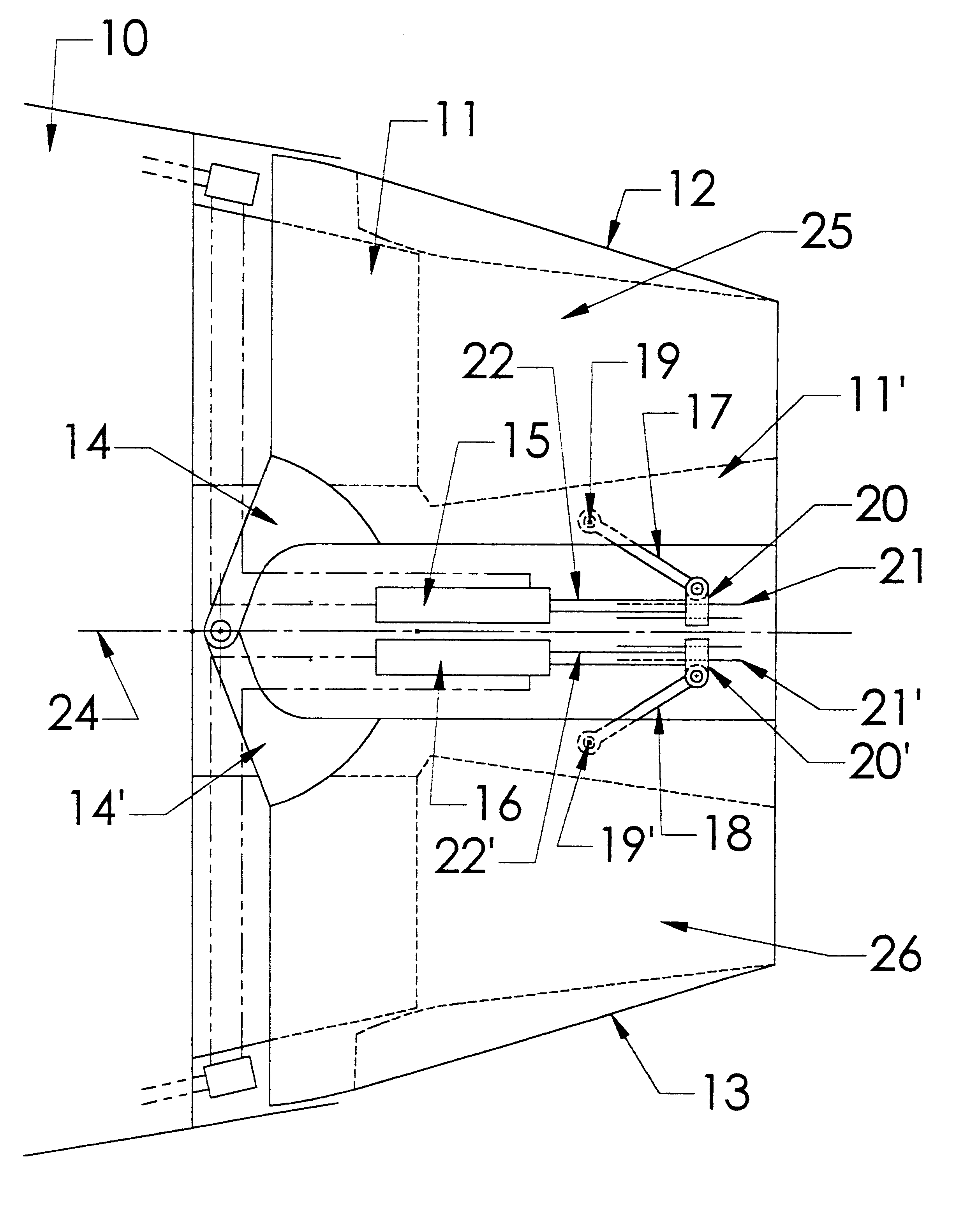
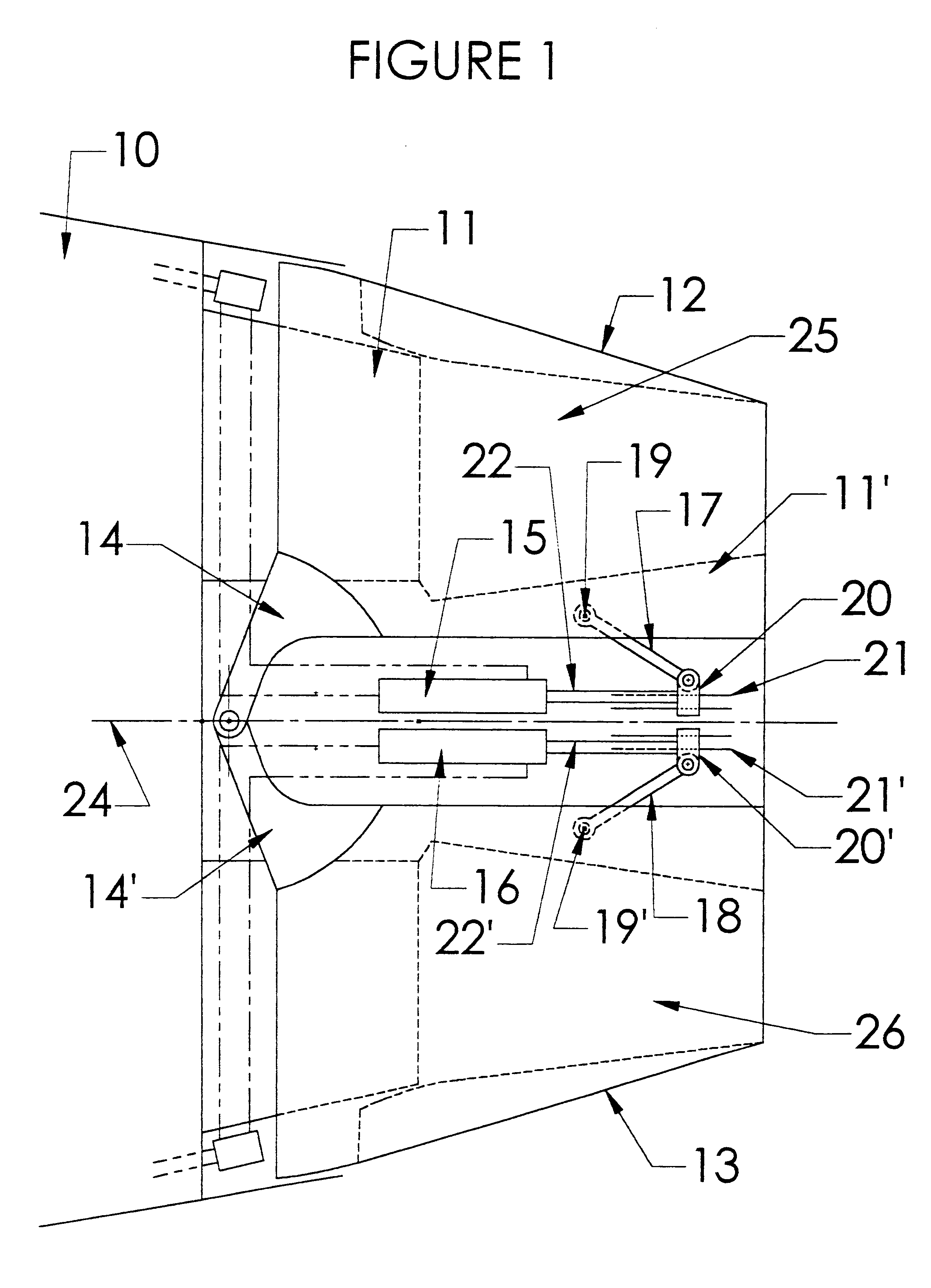
With reference to FIG. 1, in the present invention, a thrust vectoring and variable exhaust area nozzle 10 for a jet engine such as a turbo-fan is provided by a fixed structure 11, first and second pivoting shell 12 and 13, a sealing system (shown in FIG. 15), and first and second actuators 15 and 16. The fixed structure 11, also called a jet pipe, is the structure that provides the support for the two pivoting shells 12 and 13, and for the actuators 15 and 16. The fixed structure 11 cooperates radially and longitudinally with the two pivoting shells 15 and 16 through a sealing arrangement that ensures fluid tightness between the respective elements.

With continued reference to FIG. 1, the rear (aft) end of the jet engine generally designated 10, includes a jet pipe 11 in which two radial cutouts 25 and 26 are provided. The radial cutouts 25 and 26 are defined by the jet pipe extensions 11' (only one of which is shown as a result of the side view of the nozzle). The first and second ...

second embodiment

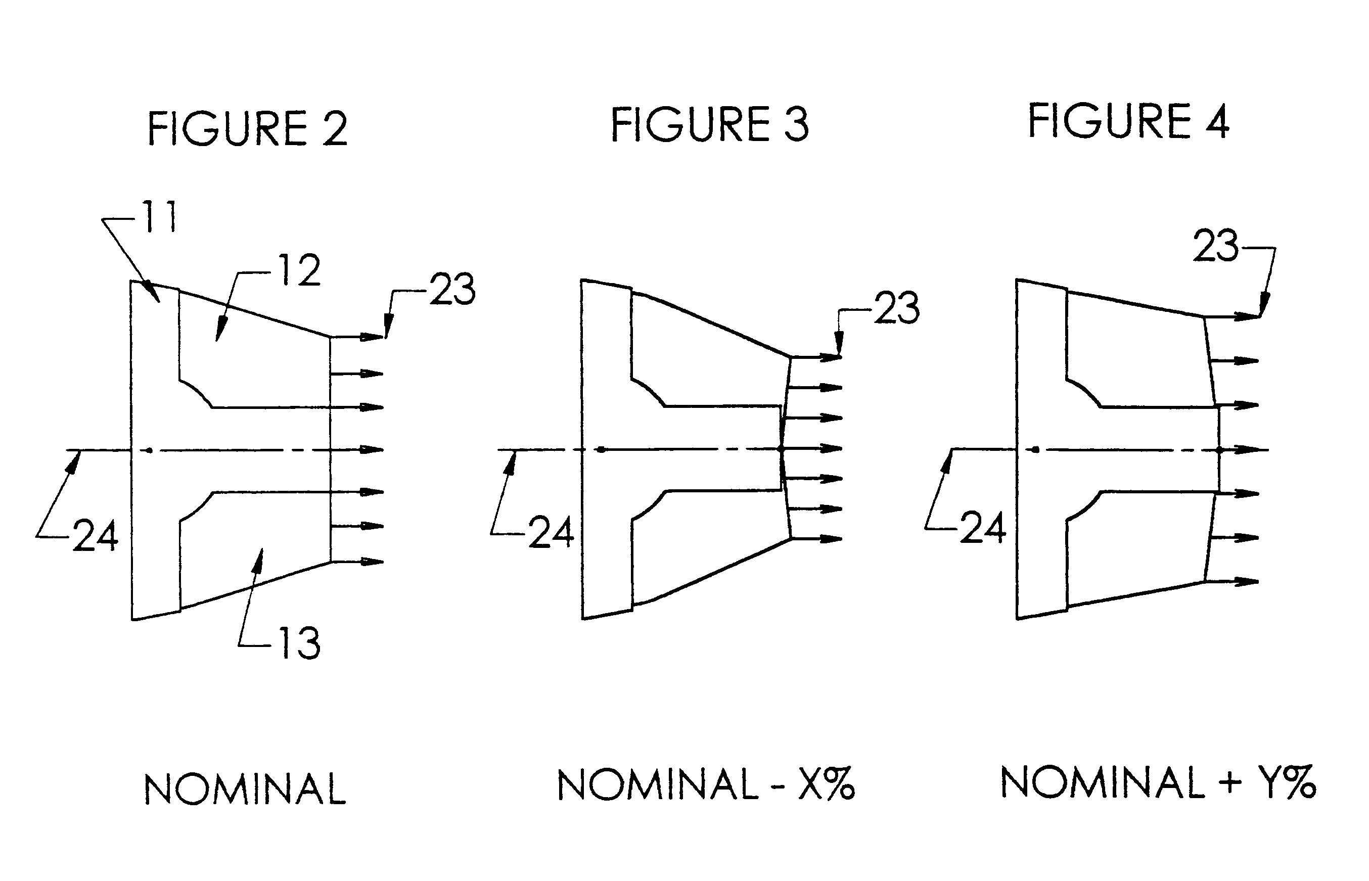
With reference to FIG. 10, the invention is shown in which like reference numerals refer to like elements. The difference between the embodiments shown in FIGS. 1 and 10 is that in the later embodiment the actuators 215 and 216 are connected to the shells 212 and 213 at points along the leading edge of the shells, and the later embodiment shows a nozzle with an internal convergent-divergent profile. The independent actuators 215 and 216 are connected to the jet pipe 11 through pivot connections 217 and 219, respectively. The actuators 215 and 216 are also connected to the shells 212 and 213 through pivot connections 218 and 220. As with the embodiment shown in FIG. 1, pivoting may be symmetrical to provide variable exit nozzle areas as shown in FIGS. 13 and 14. Alternatively, pivoting may be asymmetrical to vary the thrust vector angle as shown in FIGS. 11 and 12.

As also shown in FIG. 10, a first control arm 221 is pivotally connected to the first shell 212 through a pivot pin 222. ...


PUM


Abstract

A variable area exhaust nozzle with a variable thrust vector angle for a turbo-fan engine and mounted on the aft portion of the nacelle which wraps said engine. The nozzle may include a fixed structure having at least two lateral arms separating two radial cutouts. The cutouts are positioned one above the other, one being located above the engine axis, the other one below the engine axis. At least two shells close the fixed structure cutouts and are pivotally mounted on the fixed structure to form a portion of the exhaust nozzle of the engine. A sealing means ensures fluid tightness between the shells and the fixed structure for any angular position of said shells. Actuator means are provided for pivoting the shells either to a symmetrical configuration for changing of the value of the exhaust area of the nozzle or to an unsymmetrical configuration for changing the angle of the thrust vector of the exhaust nozzle. In operation, the value of the exhaust area and the thrust vector angle of the exhaust nozzle are varied during flight to optimize performance of the aircraft.

Description

The present invention relates to an exhaust nozzle for jet engines. Such a nozzle may be used on business aircraft and for commercial aircraft for optimizing their take-off, climb and cruise performance, as well as for increasing safety in flight and reducing speed at landing.Variable area exhaust nozzles are known in the art. For example, U.S. Pat. No. 5,221,048, which is incorporated by reference herein, describes a variable exhaust area nozzle comprising a fixed structure having mounted thereon two pivoting half shells that cooperate radially and longitudinally with said fixed structure. The two shells and the fixed structure on which they are mounted form the rear part of the nacelle that encloses the engine. Thus, the two shells and the fixed structure form the exhaust nozzle of the engine. Fluid tightness between the two half shells and the fixed structure is provided by a sealing arrangement. Actuators are used to pivot the shells into any position between their fully opened ...

Claims


Application Information

Patent Timeline
Patent Type & Authority Patents(United States)
IPC IPC(8): B64C15/00B64C15/02F02K1/11F02K1/54F02K1/15F02K1/70F02K1/60F02K1/04F02K1/76F02K1/00F02K1/80
CPCB64C15/02F02K1/002F02K1/006F02K1/04F02K1/11F02K1/15F02K1/60F02K1/70F02K1/76F02K1/805F02K1/54F05D2240/55Y02T50/672Y02T50/60
Inventor LAIR, JEAN-PIERRE
Owner PROPULSION VECTORING
Why Eureka
Try Eureka