Electronic identification system

a technology of electronic identification system and identification plate, applied in the field of electronic identification plate, can solve the problems of relatively sophisticated anti-theft gate and anti-theft gate triggered

Inactive Publication Date: 2003-04-15
INT COMP LTD
View PDF11 Cites 136 Cited by
  • Summary
  • Abstract
  • Description
  • Claims
  • Application Information

AI Technical Summary

Problems solved by technology

However, a problem with this is that if the customer later brings the purchased goods back into the store with the transponder still attached, the anti-theft gate will be triggered.
However, a problem with this proposal is that it requires a relatively sophisticated anti-theft gate, capable not only of detecting the presence of a transponder, but also of interrogating it to read the information indicating whether the article has been paid for.

Method used


Image

  • Electronic identification system
  • Electronic identification system
  • Electronic identification system

Examples


Embodiment Construction

One embodiment of the invention will now be described by way of example with reference to the accompanying drawings.

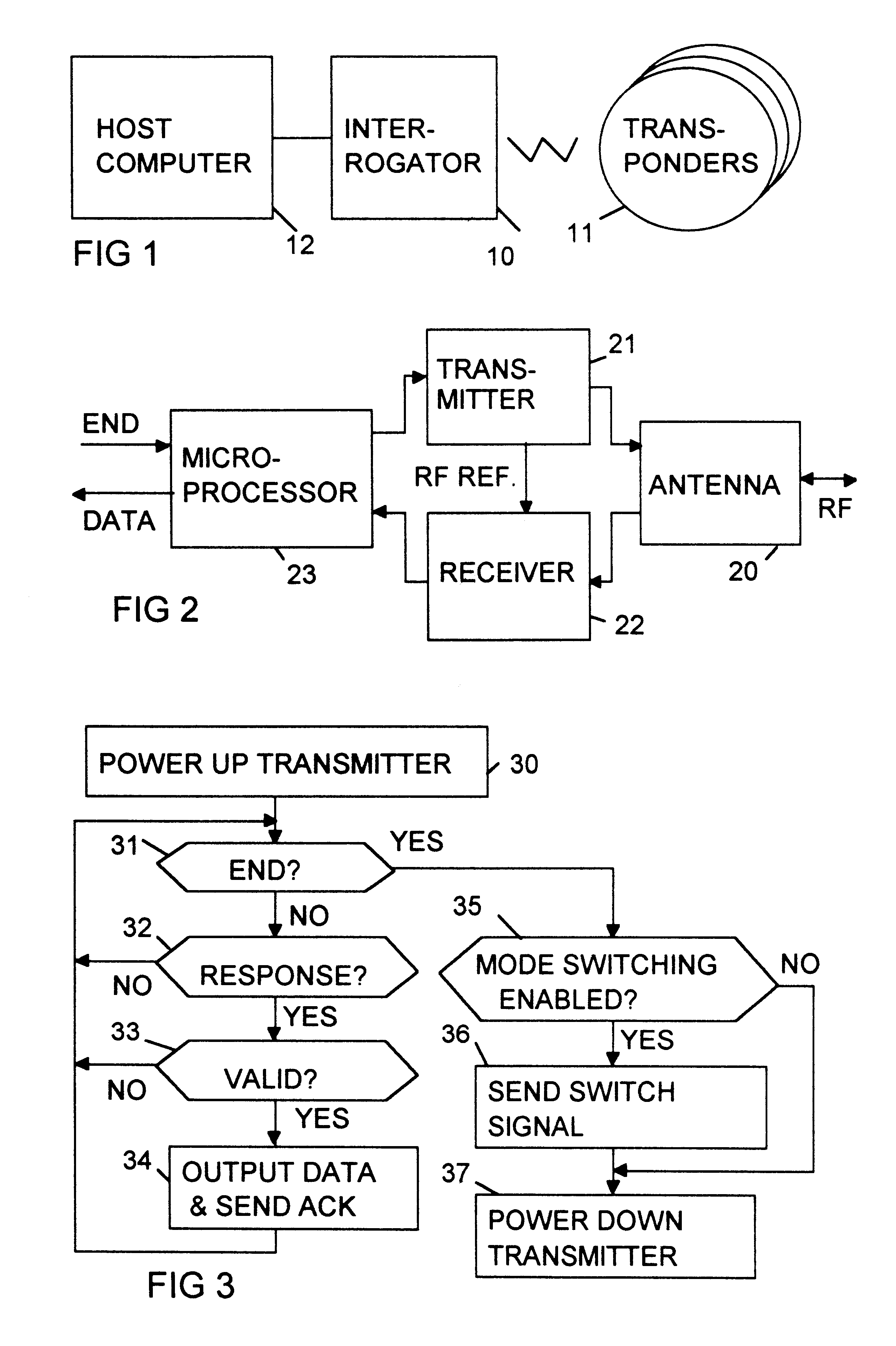
Referring to FIG. 1, this shows an electronic identification system comprising an interrogator 10 and a plurality of transponders 11. The transponders may, for example, be incorporated into tags or labels attached to goods in a retail store, while the interrogator may be built into a checkout station in the store. The interrogator is connected to a host computer 12.

Referring to FIG. 2, this shows the interrogator in more detail. The interrogator comprises an RF antenna 20, a transmitter circuit 21, a receiver circuit 22, and a controlling microprocessor 23. The antenna 20 is connected to both the transmitter and receiver circuits, and serves both for transmission and reception. The transmitter circuit is controlled by the microprocessor and, when powered up, generates an interrogation signal, comprising a continuous RF carrier signal.

As will be described, any transpond...


PUM


Abstract

An identification system, e.g. for tagging goods in a retail store, has at least one interrogator and a number of transponders for attaching to goods. Each transponder responds to an interrogation signal from the interrogator by returning a response signal containing information stored in the transponder. The transponder can be switched, by means of a mode switching signal from the interrogator, into a reduced power mode in which the power level of the response signal is reduced from its normal level. The reduced power mode may for example be selected when the goods have been paid for, to ensure that the transponder does not trigger an anti-theft gate, which can detect only the normal power level. The transponder can, however, still be read by an interrogator capable of detecting the reduced power level, e.g. at a customer services desk.

Description

BACKGROUND TO THE INVENTIONThis invention relates to an electronic identification system comprising a plurality of transponders, and an interrogator for interrogating the transponders to obtain information stored in the transponders. The invention also relates to a transponder for use in such an identification system. The invention is particularly, although not exclusively, concerned with an electronic identification system using radio frequency (RF) technology for communication between the interrogator and the transponders.Such an electronic identification system is described for example in European Patent Applications EP 0494114, EP 0585132 and EP 0598624, and in PCT Patent Application WO 93 / 17404.Such systems have many potential applications, such as tagging goods, mail, vehicles or animals. For example, such a system could be used in a retail store to identify goods presented by a customer at a checkout. The transponders could be incorporated in tags attached to the goods or to ...

Claims


Application Information

Patent Timeline
Patent Type & Authority Patents(United States)
IPC IPC(8): G06K7/00G07C9/00G01S13/75G01S13/76G01S13/78G01S13/79G08B13/24
CPCG06K7/10059G06K7/0008
Inventor TURNER, EDWIN
Owner INT COMP LTD
Why Eureka
Try Eureka