Remote-controlled camera-picture broadcast system

a remote control and camera technology, applied in the field of remote control camerapicture broadcast system, can solve the problems of high hardware and network cost to ensure or secure satisfactory performance, high hardware and network cost, and the need for maintenance of camera control server softwar

Inactive Publication Date: 2003-04-29
NEC CORP
View PDF8 Cites 164 Cited by
  • Summary
  • Abstract
  • Description
  • Claims
  • Application Information

AI Technical Summary

Problems solved by technology

With the conventional remote-controlled camera-picture broadcast system disclosed in the Japanese Non-Examined Patent Publication No. 8-265742 as described above, however, there are the following three problems.
A first problem is that the cost of the hardware and the network becomes high to ensure or secure the satisfactory performance of the conventional broadcast system even for the use of a lot of unspecified users.
These facts require the high performance of not only the camera control server software and the first workstation but also the network connected thereto, resulting in high cost of the hardware and the network.
A second problem is that the necessity of maintenance of the camera control server software and the first workstation becomes high in order to ensure the stable operation for a lot of unspecified users.
The second problem is caused by the fact that the camera control server software and the first workstation tend to operate unstably due to load change and/or unjust access since the broadcast system is used by a lot of unspecified users.
A third problem is that the overhead tends to be large on use by

Method used


Image

  • Remote-controlled camera-picture broadcast system
  • Remote-controlled camera-picture broadcast system
  • Remote-controlled camera-picture broadcast system

Examples


first embodiment

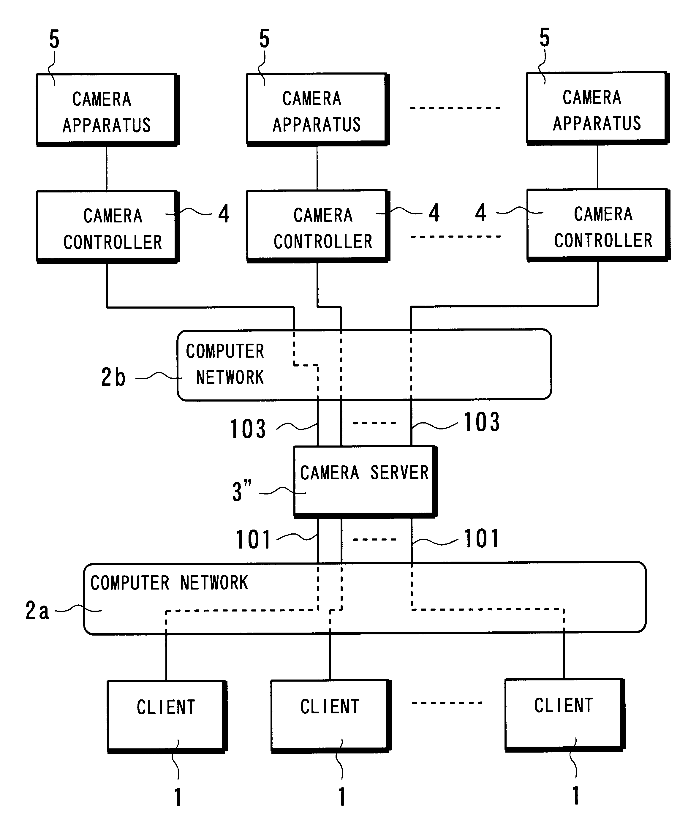
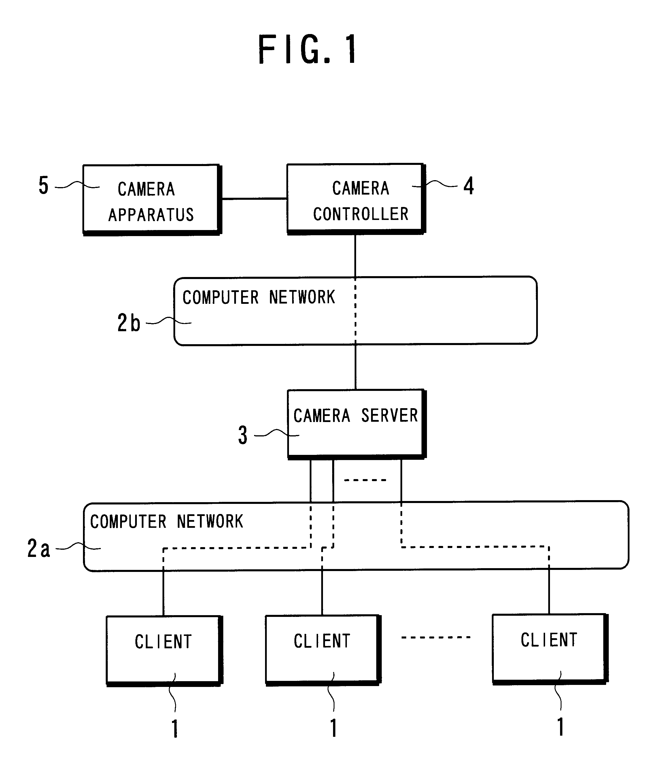
As shown in FIG. 1, a remote-controlled camera-picture broadcast system according to a first embodiment of the present invention is comprised of clients 1, a camera server 3 connected to the clients 1 through a computer network 2a, a camera controller 4 connected to the camera server 3 through a computer network 2b, and a camera apparatus 5 connected directly to the camera controller 4.

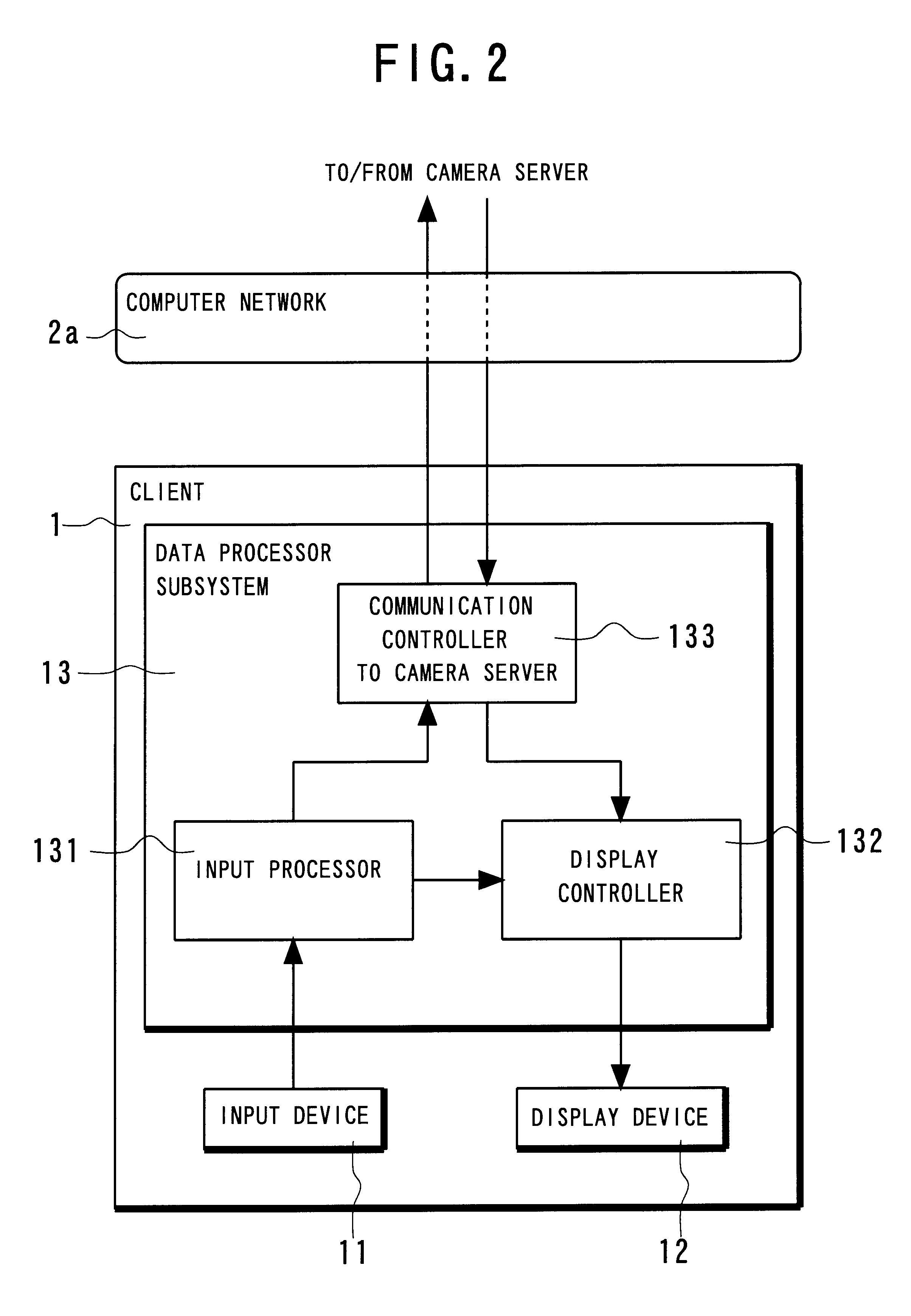
Each of the clients 1 receives an input from a user and displays an output on its screen.

The camera apparatus 5, which is capable of various operations such as rotation and zooming under the control of the camera controller 4, acquires a moving picture and outputs a video signal of the picture to the camera controller 4.

The camera controller 4, which controls the camera apparatus 5, receives the video signal of the picture that has been acquired or shot in the camera apparatus 5, converts the video signal to a picture data, and transmits the picture data to the client 1 in question.

The camera server 3...

second embodiment

FIGS. 8 and 9 show the operation of the clients 1 and the camera server 3 of a remote-controlled camera-picture broadcast system according to a second embodiment of the present invention, respectively.

The system according to the second embodiment has the same configuration as that of the first embodiment except that the operation of the clients 1 and the camera server 3 are different. Therefore, the structural explanation of the system is omitted here for the sake of simplification.

As shown in FIG. 8, the operation of the clients 1 is the same as the first embodiment except that the steps A 105 to A107 in the flowchart of the first embodiment of FIG. 5 are omitted.

As shown in FIG. 9, the operation of the camera server 3 is the same as the first embodiment except that the step A 304 in the flowchart or the first embodiment of FIG. 6 is omitted.

FIG. 14 schematically shows the concrete operation of the remote-controlled camera-picture broadcast system according to the second embodiment...

third embodiment

FIGS. 10A and 10B, 11A and 11B, and 12 show the operation of the clients 1, the camera server 3, and the camera controller 4 of a remote-controlled camera-picture broadcast system according to a third embodiment of the present invention, respectively.

The system according to the third embodiment has the same configuration as that of the first embodiment except that the operation of the clients 1, the camera server 3, and the camera controller 4 are different. Therefore, the structural explanation of the system is omitted here for the sake of simplification.

The operation of the client 1 is substantially the same as that of the first embodiment except for the following difference.

As shown in FIGS. 10A and 10B, prior to the judgment whether the feedback is transmitted from the camera server 3 or not in the step A108, the communication controller 133 of the client 1 judges whether the in-operation data is transmitted from the camera server 3 or not in the step B101. Here, the in-operatio...


PUM


Abstract

A remote-controlled camera-picture broadcast system is provided, which decreases the cost of hardware and network for the use of a lot of unspecified users. This system is comprised of a camera apparatus, a camera controller, a camera server connected to the camera controller through a first network, and clients connected to the camera server through a second network. Each of the clients transmits an operation demand for the camera apparatus to the camera server through the second network according to an input of a user. The camera server receives the operation demand from the client into which the input of the user is applied, and transmits an operation command corresponding to the operation demand to the camera controller through the first network. The camera controller controls the camera apparatus according to the operation command from the camera server so that the camera apparatus acquires a picture and produces a video signal of the picture. The camera controller receives the video signal of the picture produced by the camera apparatus, converts the video signal to a picture data, and transmits the picture data to the camera server through the first network. The camera server transmits the picture data through the second network to the client from which the operation demand has been transmitted, thereby displaying the picture of the picture data on a screen.

Description

1. Field of the InventionThe present invention relates to a remote-controlled camera-picture broadcast system and, more particularly, to a remote-controlled camera-picture broadcast system that facilitates use by a potentially large plurality of unspecified users through a computer network and which is applicable to a video monitoring system.2. Description of the Prior ArtConventionally, the remote-controlled camera-picture broadcast systems of this sort have been used to acquire a picture by operating or controlling at least one video camera mounted at a distant place through a computer network.An example of the conventional remote-controlled camera-picture broadcast systems is disclosed in the Japanese Non-Examined Patent Publication No. 8-265742 published in 1996, which is comprised of a first workstation to which a video camera is connected, a second workstation, a third workstation to which a display monitor is connected, and a fourth workstation to which a display monitor is c...

Claims


Application Information

Patent Timeline
IPC IPC(8): H04N5/232H04N5/00G06F13/00H04N7/18
CPCH04N5/23206H04N5/232H04N23/661H04N23/63
Inventor YOSHIMURA, NAOTOOHNO, HIDEOOKANO, HISASHI
Owner NEC CORP
Why Eureka
Try Eureka