LED lighting equipment for vehicle

a technology for lighting equipment and vehicles, applied in the direction of lighting and heating equipment, fixed installations, instruments, etc., can solve the problems of increasing cost, power consumption, temperature when turned on, etc., and affecting the load of vehicles

Inactive Publication Date: 2003-05-06
STANLEY ELECTRIC CO LTD
View PDF9 Cites 110 Cited by
  • Summary
  • Abstract
  • Description
  • Claims
  • Application Information

AI Technical Summary

Problems solved by technology

In order to solve this problem, the radiation angle of respective LED lamps 92 may be overlapped each other, by reducing the LED lamp 92 arrangement distance, or increasing the depth of the LED lighting equipment for vehicle; however, if the distance is reduced, the necessary number of LED lamps 92 for the same light emitting surface, resulting in increase of cost, power consumption, temperature when turned on, or other problems, and if the depth is increased, the size also increasing, making difficult to load on a vehicle and causing other new problems.

Method used


Image

  • LED lighting equipment for vehicle
  • LED lighting equipment for vehicle
  • LED lighting equipment for vehicle

Examples


first embodiment

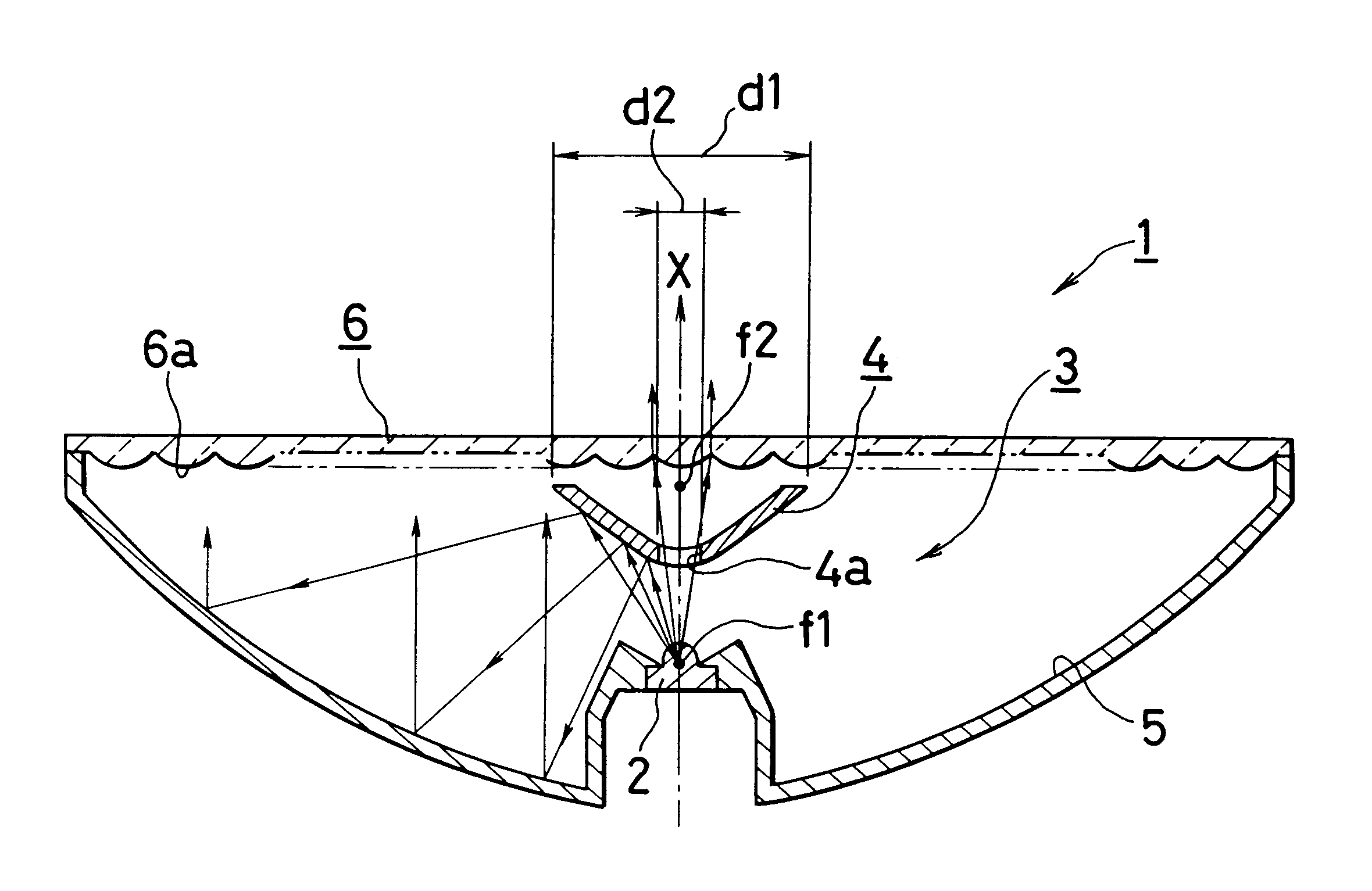
Now, the present invention will be described in detail, based on the embodiment shown in the drawing. In FIG. 1, the symbol 1 indicates a lighting equipment for vehicle according to the present invention, adopting an LED lamp 2 as in the prior art; however, in this invention, the LED lamp 2 is provide with a light emitting unit 3.

Said light emitting unit 3 comprises, as main components, a reflection surface of hyperboloid 4 having a transmission portion, and a reflection surface of paraboloid of revolution 54, and said LED lamp 2 is disposed at a predetermined position in respect to said reflection surface of hyperboloid 4.

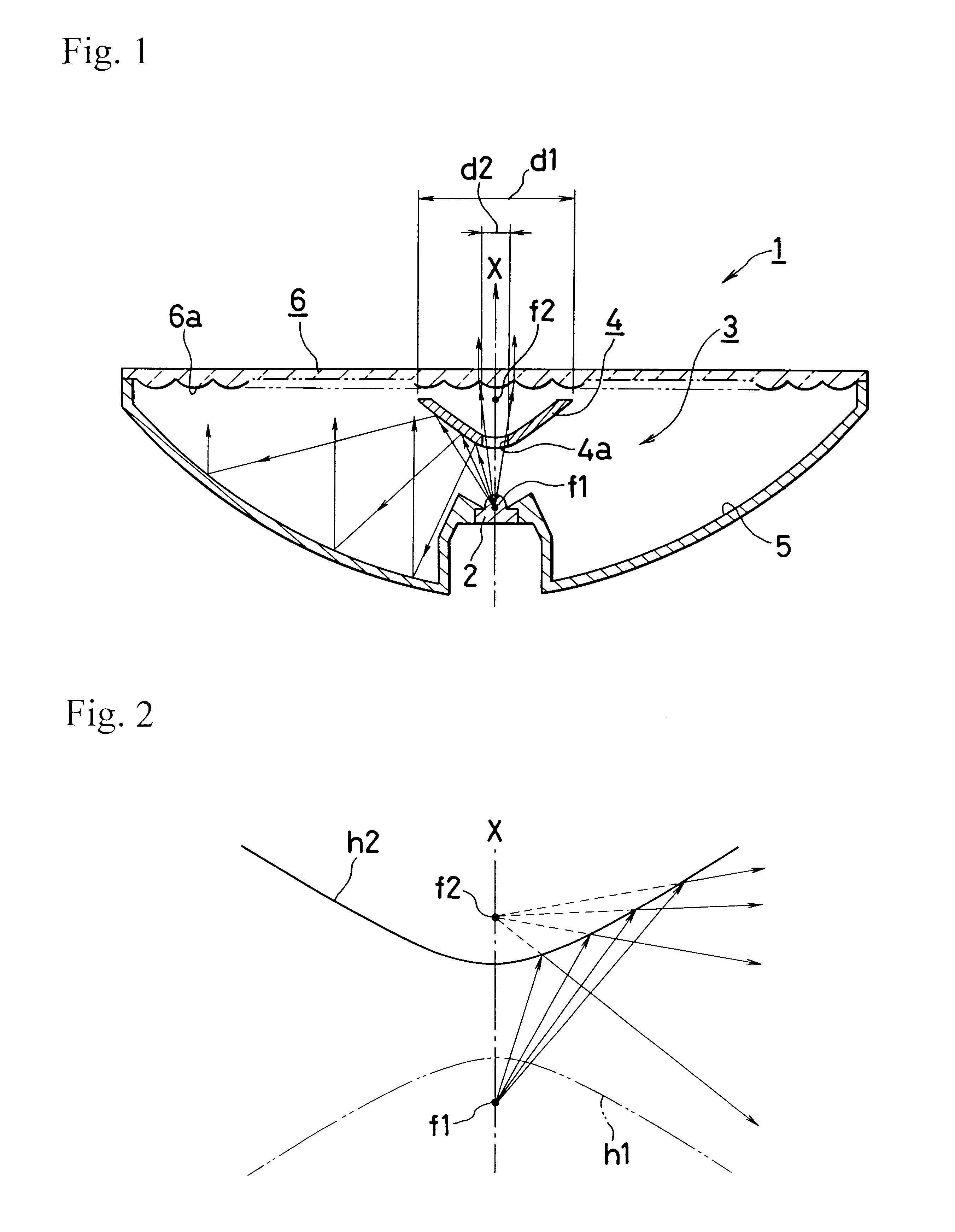
Before describing the lighting equipment for vehicle 1 of the present invention, the properties of hyperbola will be explained briefly. As shown in FIG. 2, a pair of hyperbolae h1, h2 facing each other have respectively foci f1, f2. A hyperboloid of two sheets facing each other with both convex faces is obtained by the rotation of the hyperbolae h1, h2 around an a...

second embodiment

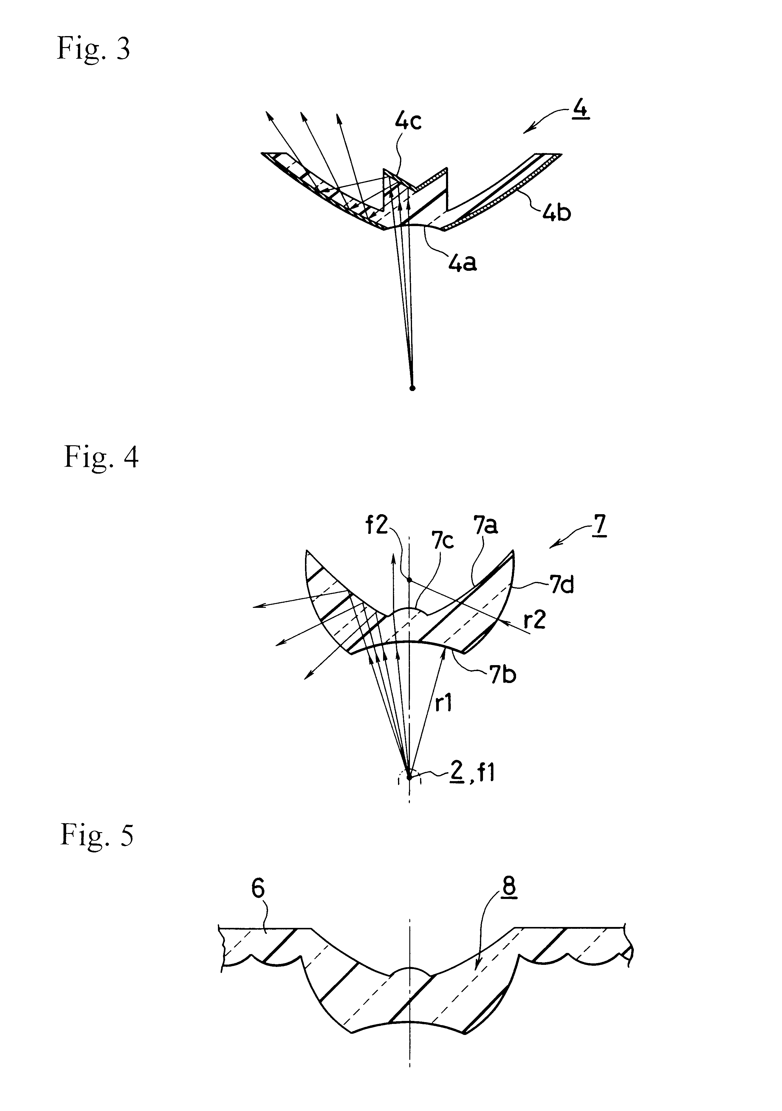
FIG. 3 shows the present invention, and this second embodiment concerns said reflection surface of hyperboloid 4. In the general characteristics of the LED lamp 2, light amount directed in the irradiation direction X is overwhelmingly important, and it is expected that the light amount passing through the transmission portion 4a is considerably high, though the aforementioned transmission portion 4a is small in diameter.

Consequently, it is preferable to diverge the light passing through said transmission portion 4a over an area as large as possible, for taking the balance of brightness with the other portions such as refection surface of paraboloid of revolution 5; therefore, in this second embodiment, a full reflection surface 4c made, for instance, in a substantially conical form, is provided on the optical path from said transmission portion 4a and light is reflected on the back of the reflection surface of hyperboloid 4 to enhance the divergence. Here, in this second embodiment,...

third embodiment

In opposition, the reflection surface of hyperboloid 7 of this third embodiment, the function of full reflection generating at the interface in a transparent resin at the critical angle produced by the difference of the transparent resin refractive index and the atmospheric refractive index is used and, in this embodiment, the hyperboloid 7a is formed at the interface with the atmosphere at the back of the transparent member viewed from the LED lamp 2.

The convenient range for the incident position of the light from the LED lamp 2 is made as an arc r1 surface around the first focus f1 or a plane, to form a transmission portion incidence portion 7b, and the back portion corresponding to said transmission portion incidence portion 7b is made as a convenient convex lens shape or others, to form a transmission portion exit portion 7c. Here, the diameter of the transmission portion exit portion 7c is decided similarly to the foregoing first embodiment.

A face 7d at the LED lamp 2 side whic...


PUM


Abstract

In the conventional lighting equipment for vehicle using LED lamp, as the LED lamp irradiation angle is narrow, an optical irregularity making the luminescent surface spotted is generated, resulting in a feeling of wrongness of the viewer. Means to Solve the Problem. A LED lighting equipment 1 for vehicle of the present invention, comprising at least one light emitting unit 3 wherein an LED lamp 2 is disposed approximately at the focus of one hyperboloid, a reflection surface of hyperboloid 4 defined by the other hyperboloid comprising a transmission portion 4a disposed in an appropriate range near the optical axis is arranged in the LED lamp 2 optical axial direction, and a refection surface of paraboloid of revolution 5 having the approximate focus at the focus of said the other hyperboloid focus is arranged at the side of said LED lamp 2, allows to enlarge the irradiation angle at the reflection surface of hyperboloid 4, and to emit light in a larger area.

Description

1. Field of the InventionThe present invention relates to a composition of a lighting equipment for vehicle adopting one or a plurality of LED lamps as light source, and more precisely, has an object to provide a composition allowing to prevent irregular brightness over the light emitting surface that appears frequently when the LED lamp is adopted as light source from occurring.2. Detailed Description of the Prior ArtFIG. 6 shown an example of composition of a conventional LED lighting equipment 90 for vehicle, wherein an LED lamp 92 is fitted to each of individual reflector portion 91a, of a base plate 91 where a plurality of reflector portions 91 for example as surface of paraboloid of rotation are formed, and further, the front of said LED lamp 92 is covered with a lens 93 provided with a lens cut 93a corresponding to each of individual reflector portion 91a.In such a composition, the direct light from the LED lamp 92 and the light reflected from said reflector portion 91a are i...

Claims


Application Information

Patent Timeline
Patent Type & Authority Patents(United States)
IPC IPC(8): F21V7/00F21S8/10F21V11/08F21V13/04F21W101/12F21W101/14F21Y101/02
CPCF21S48/1388F21S48/215F21S48/236F21S48/24G02B19/0061F21V7/0091G02B19/0071G02B19/0028F21V7/0041F21V7/0016F21V11/08F21S41/143F21S41/151F21S41/28F21S41/321F21S41/322F21S41/365F21S43/14F21S43/26F21S43/31F21S43/315F21S43/40
Inventor KONDO, TOSHIYUKIOKADA, HIDETAKA
Owner STANLEY ELECTRIC CO LTD
Why Eureka
Try Eureka