
Running wheel arrangement

a running wheel and arrangement technology, applied in the direction of high resiliency wheels, skate boards, vehicle components, etc., can solve the problems of reducing driving comfort, significant load on joints, and inability to absorb shocks on a single wheel of inline skates

Inactive Publication Date: 2003-05-13
LITENS AUTOMOTIVE GMBH
View PDF14 Cites 3 Cited by
  • Summary
  • Abstract
  • Description
  • Claims
  • Application Information

AI Technical Summary

Benefits of technology

Since the hub means according to the invention comprises an internal hub, which can be connected to the inline skate by means of an axis, and an external hub which is provided in a manner fixed for co-rotation with respect to the internal hub and is movable with respect to the internal hub in the radial direction, the wheel arrangement may move substantially perpendicularly with respect to the inline skate. The spring means which is provided between the internal hub and the external hub can absorb shocks against the individual wheel arrangements of the inline skate in the direction of movement of the wheel arrangement with respect to the inline skate. Thus, the driving comfort is increased and at the same time, the joints of the inline skater are protected.
Advantageously, the rim may be secured at the ball bearing or the roller bearing by means of a safety ring. Since such a safety ring can be easily attached and released, a simple installation is also ensured by this measure. This may enable an exchange of individual components, e.g. of the bearing means.

Problems solved by technology

A disadvantage of this known wheel arrangement is, however, that shocks on a single wheel of the inline skates cannot be absorbed but are rather transferred onto the inline skate.
Shocks of this type reduce the driving comfort and also lead to a significant load on the joints.
Furthermore, the known wheel arrangement is susceptible to vibrations particularly at high running speeds.

Method used


Image

  • Running wheel arrangement
  • Running wheel arrangement
  • Running wheel arrangement

Examples


Embodiment Construction

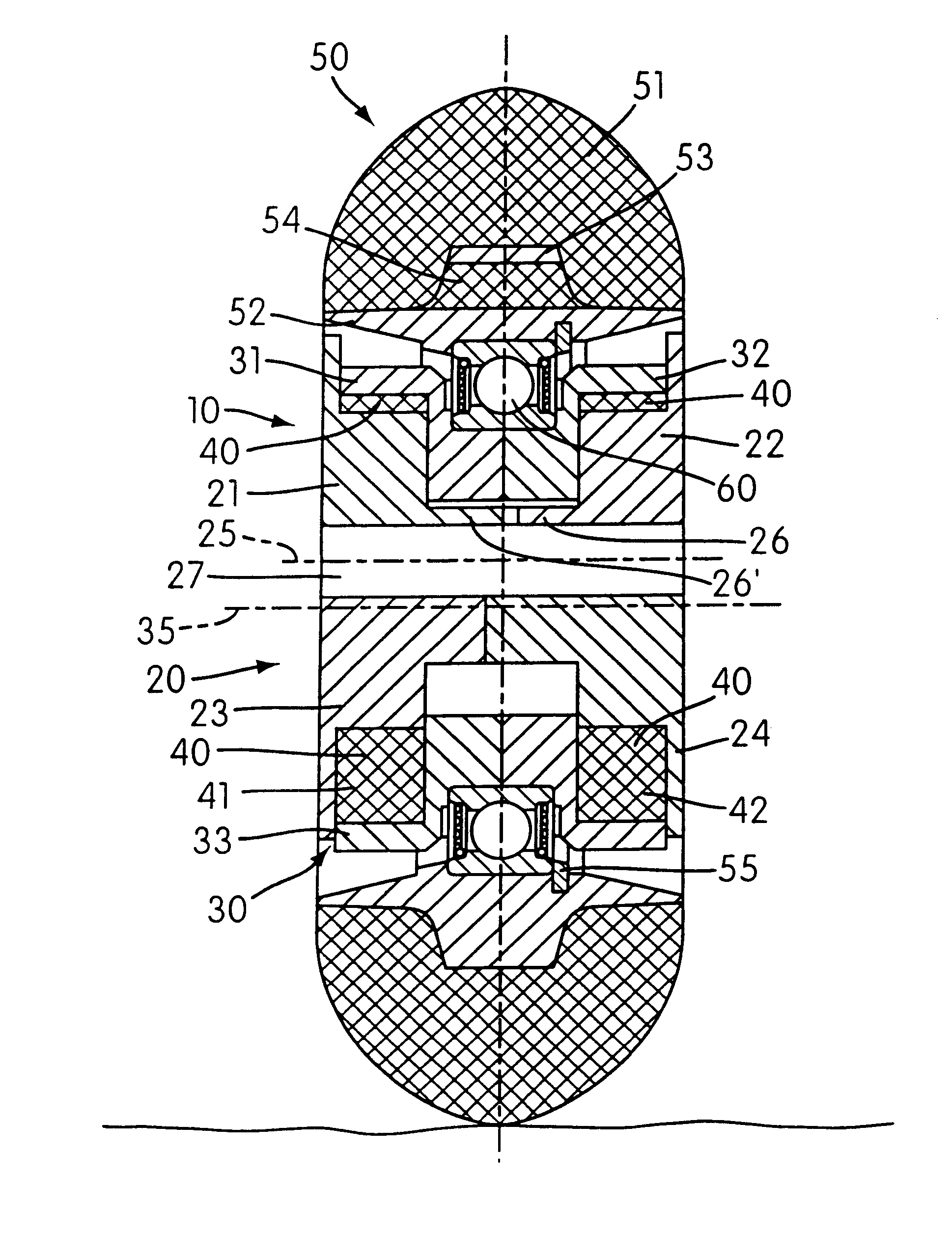
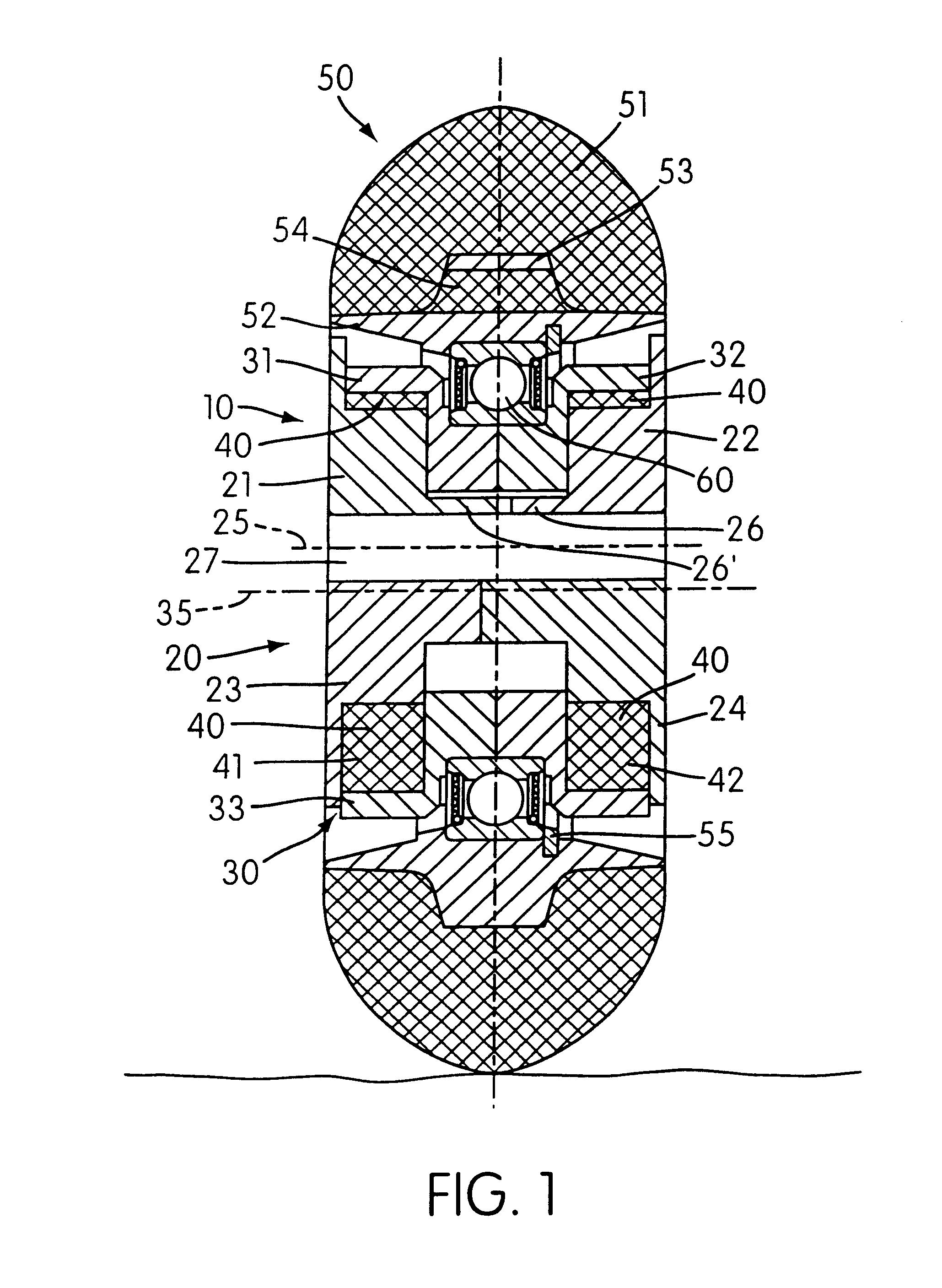
This wheel arrangement comprises a hub means 10 and a running wheel 50, which is rotatably supported on the hub means 10.

The hub means according to the embodiment shown comprises an internal hub 20 and an external hub 30. The internal hub as well as the external hub 30 in turn consist of two halves each, i.e. of two internal hub halves 21 and 22 and two external hub halves 31 and 32.

A spring element in the form of an elastic body 41a,b is provided between the first internal hub half 21 and the first external hub half 31. Similarly, a spring element [42] is arranged between the second internal hub half 22 and the second external hub half 32.

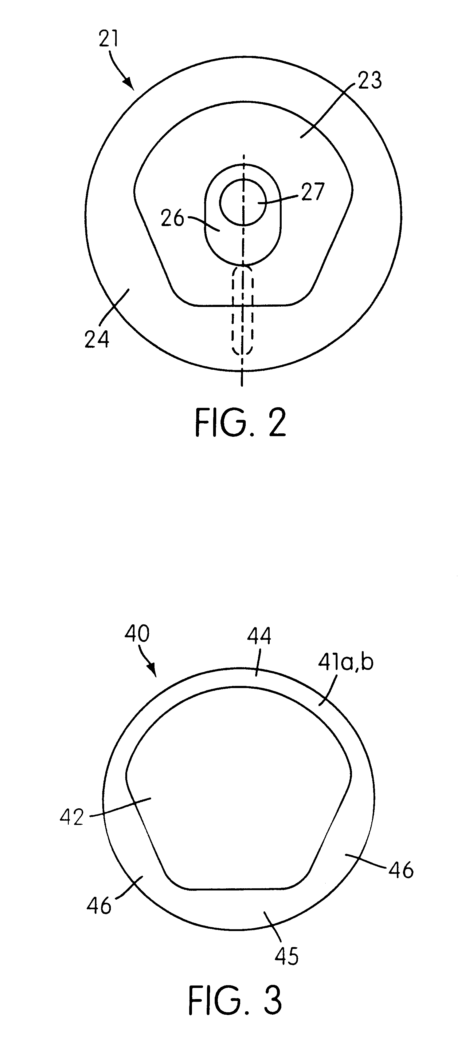
In FIG. 2 and 3, to which reference will now be made, a plane view onto the internal hub half 21 and a plane view onto the spring element 41 is shown.

As may be seen in FIG. 3, the spring element consists of an elastic body 41a,b which comprises an opening 42.

The internal hub half 21 shown in FIG. 2 in plane view comprises a circular and plate-shap...


PUM


Abstract

The present invention relates to a running wheel arrangement having a hub and a running wheel, which is rotatably supported on the hub. Furthermore, the hub includes an internal hub and an external hub which are provided substantially in a manner fixed for co-rotation and which are displaceable against each other in the radial direction. The running wheel further includes a spring which is provided between the internal hub and the external hub.

Description

The present invention relates to a running wheel arrangement having a hub means and a running wheel rotatably supported on the hub means.SUMMARY OF RELATED ARTRunning wheel arrangements of this type are used in sporting devices such as inline skates. Running wheel arrangements of this type consist, in particular, of a wheel body made of polyurethane, and a rim fixedly connected to this wheel body. The rim in turn, is rotatably supported on a hub. The hub is finally attached by means of a shaft at a support provided at the inline skates.A disadvantage of this known wheel arrangement is, however, that shocks on a single wheel of the inline skates cannot be absorbed but are rather transferred onto the inline skate. Shocks of this type reduce the driving comfort and also lead to a significant load on the joints.Furthermore, the known wheel arrangement is susceptible to vibrations particularly at high running speeds.SUMMARY OF THE DISCLOSUREIn view of the above-mentioned facts, the objec...

Claims


Application Information

Patent Timeline
Patent Type & Authority Patents(United States)
IPC IPC(8): A63C17/00A63C17/22
CPCA63C17/223
Inventor GUHR, WOLFGANG
Owner LITENS AUTOMOTIVE GMBH
Learn More