
Method and device for operating a drive device, drive device

a technology of drive device and drive shaft, which is applied in the direction of propulsion parts, mechanical equipment, transportation and packaging, etc., to achieve the effects of increasing driving comfort, uniform buildup of torque, and reducing the risk of accidents

Active Publication Date: 2020-05-26
ROBERT BOSCH GMBH
View PDF11 Cites 0 Cited by
  • Summary
  • Abstract
  • Description
  • Claims
  • Application Information

AI Technical Summary

Benefits of technology

[0004]The method according to the invention has the advantage that the shifting delay or a delay or interruption in the tractive force which can be felt by the driver or the occupants of the motor vehicle is reduced further compared to known solutions and is under certain circumstances completely suppressed. As a result, on the one hand, the driving comfort is increased and, on the other hand, advantages with respect to the driving safety are achieved or ensured on the basis of a uniform buildup of torque at the driven wheels.
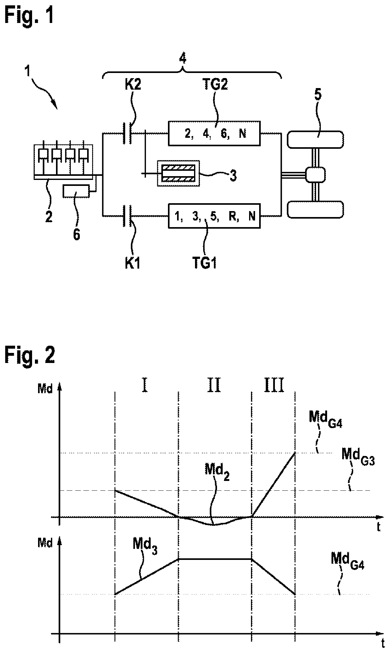
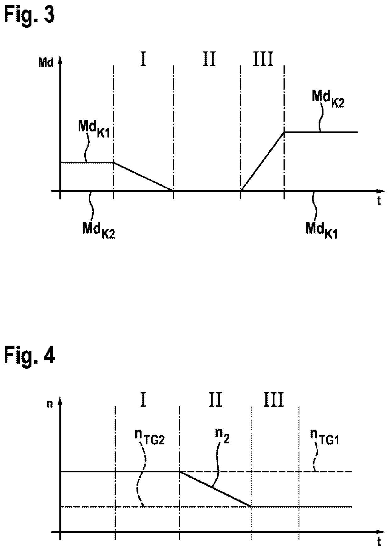
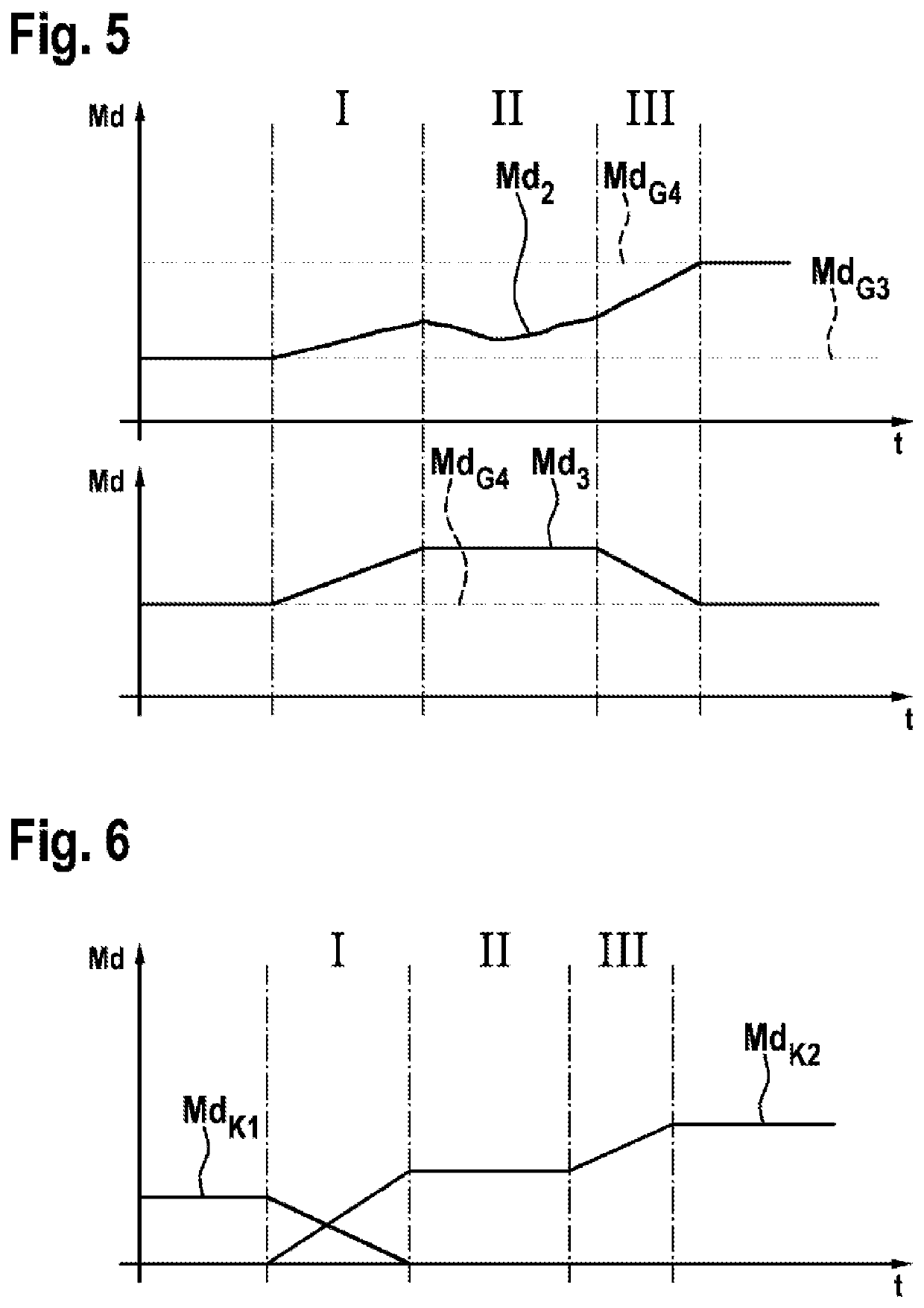
[0007]According to one preferred development of the invention there is provision that in order to initiate the gear shifting process the torque which is transmitted by the internal combustion engine to the dual-clutch transmission is reduced. The gear shifting process is therefore initiated by virtue of the fact that the torque which is made available by the internal combustion engine is reduced. This reduction is expediently completely or partially compensated by the electric machine, as already described above. In particular, the compensation takes place in such a way that the engine torque of the internal combustion engine is continuously reduced and the machine torque of the electric machine continuously increased, in order to bring about the changeover between the generator of the drive torque without an interruption in the tractive force at the driven wheels.
[0009]Alternatively or additionally there is preferably provision that the torque which is transmitted from the internal combustion engine to the dual-clutch transmission is provided by reducing the engine torque of the internal combustion engine. The engine torque or a target internal combustion engine torque corresponds to the target drive torque in the case in which the drive torque is made available solely by the internal combustion engine in the initial state. If the drive torque is generated by the internal combustion engine and the electric machine together, the target engine torque corresponds to the portion of the drive target torque which is made up by the internal combustion engine torque. In particular, the engine torque of the internal combustion engine is decreased or reduced even before the clutch which connects the internal combustion engine currently to the dual-clutch transmission is opened. As a result, the engine torque which falls away is compensated by the electric machine even before the internal combustion engine is disconnected from the dual-clutch transmission in order to carry out the shifting process.
[0011]Furthermore, there is preferably provision that the clutch which connects the internal combustion engine to the dual-clutch transmission is not opened until the torque of the internal combustion engine is reduced of zero. As a result, the clutch which connects the internal combustion engine to the dual-clutch transmission is then load-free and can be opened gently with minimal wear.
[0012]Furthermore, there is preferably provision that during a rotational speed synchronization of the dual-clutch transmission during the gear shifting process both clutches are opened completely. As a result, a low-wear gear shifting process of the dual-clutch transmission is ensured. Although both clutches are opened, the embodiment according to the invention ensures that an interruption in the tractive force is prevented or that the target drive torque is at least substantially made available by the electric machine.

Problems solved by technology

However, this depends on the dimensioning of the electric machine which, under certain circumstances, can only partially provide the requested target torque.

Method used


Image

  • Method and device for operating a drive device, drive device
  • Method and device for operating a drive device, drive device
  • Method and device for operating a drive device, drive device

Examples


Embodiment Construction

[0024]FIG. 1 shows a drive device 1 of a motor vehicle, which drive device 1 is embodied as a hybrid drive device. For this purpose, the drive device 1 has an internal combustion engine 2 and an electric machine 3, which are connected by a dual-clutch transmission 4, which is illustrated only functionally in FIG. 1, to at least one driven wheel 5 of the motor vehicle. The dual-clutch transmission 4 has two clutches K1 and K2 by which it can be operatively connected to the internal combustion engine 2. In this context, the dual-clutch transmission 4 has two partial transmissions TG1 and TG2 which each have different transmission ratios and are operatively connected to the driven wheel 5. Thus, the partial transmission TG1 here has, for example, the transmission ratios for the gears 1, 3, 5, the reverse gear and a neutral gear N, while the partial transmission TG2 has the transmission ratios for the gears 2, 4 and 6 and a neutral gear N. In particular, the dual-clutch transmission 4 i...


PUM


Abstract

The invention relates to a method for operating a drive device (1) of a motor vehicle, having an internal combustion engine (2), an electric machine (3), and a dual-clutch transmission (4). The dual-clutch transmission (4) has two clutches (K1, K2), by means of which the transmission can be connected to the internal combustion engine (2). At least the internal combustion engine (2) is actuated in a driving operation in order to generate a target drive torque, and the clutches (K1, K2) are actuated in opposite directions for a gear shift. During a gear shift, the electric machine (3) which is connected to the dual-clutch transmission (4) without a clutch is actuated such that the electric machine completely or partly generates the target torque at least temporarily.

Description

BACKGROUND OF THE INVENTION[0001]The invention relates to a method for operating a drive device of a motor vehicle, which drive device has an internal combustion engine, an electric machine and a dual-clutch transmission, wherein the dual-clutch transmission has two clutches by which it can be connected to the internal combustion engine, wherein in a driving mode at least the internal combustion engine is actuated in order to generate a target drive torque, and is connected to the dual-clutch transmission by one of the clutches, and wherein the clutches are activated in opposite directions for a gear shifting process.[0002]In addition, the invention relates to a device for operating the drive device described above as well as to a corresponding drive device.[0003]Methods, devices and drive devices of the type mentioned at the beginning are basically known from the prior art. In particular, what are referred to as hybrid drive devices which, in addition to an internal combustion engi...

Claims


Application Information

Patent Timeline
Patent Type & Authority Patents(United States)
IPC IPC(8): B60W30/19B60W20/30B60W20/40F16H61/688B60W10/08B60K6/547B60W10/02B60W10/06B60K6/48B60K6/387B60W20/10B60W10/113B60W30/186F16H61/04
CPCB60K6/48B60K6/387B60W20/30B60K6/547B60W20/40F16H61/688B60W10/06B60W20/10B60W10/08B60W30/19B60W10/02B60W10/113F16H2061/0433F16H2061/0422Y02T10/6221B60K2006/4825B60W30/186B60W2710/083B60W2710/0666Y02T10/6252Y02T10/62B60Y2200/92F16H2061/0425F16H2061/0429
Inventor LUO, BENJINLEHNER, MICHAELGASPER, RAINERHUBER, THOMAS
Owner ROBERT BOSCH GMBH
Learn More