
System and method for vehicle braking

a vehicle and system technology, applied in the field of vehicle braking, can solve the problems of extreme situations in passenger vehicles, adversely affecting driving comfort, and general non-application of permanent brake systems

Inactive Publication Date: 2006-06-08
FORD GLOBAL TECH LLC
View PDF25 Cites 2 Cited by
  • Summary
  • Abstract
  • Description
  • Claims
  • Application Information

AI Technical Summary

Benefits of technology

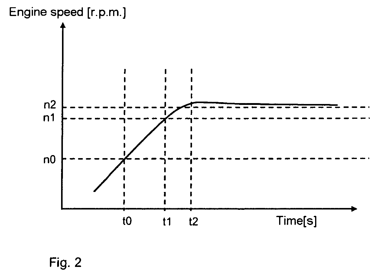
[0007] The constant engine speed leads here to a situation in which the vehicle travels down a negative gradient with a constant velocity. As a result, the driving comfort is increased, the need to use the friction brake is reduced and the driving safety is increased. It is not necessary to install an additional brake device which takes up space, for example a retarder, in this context since the braking effect is made available by the generator which is present in any case. In addition, in the operating state in which the engine speed is kept constant the generator can be used to convert a large part of the engine power into electrical power. This both reduces the need for cooling and permits the vehicle battery to be charged.
[0010] In one advantageous refinement of the method according to the invention, the checking whether the vehicle is traveling on a negative gradient is carried out repeatedly. If the checking reveals that the vehicle is no longer traveling on a negative gradient, a manipulated variable which restores the original operating state of the vehicle generator is output. This ensures that the braking effect of the vehicle generator is eliminated again after the travel on a negative gradient has ended.
[0012] In one development of the method according to the invention, checking is carried out to determine whether the vehicle is traveling on a positive gradient. If the checking reveals that the vehicle is traveling on a positive gradient, a manipulated variable for the vehicle generator is determined, which variable is suitable for placing the generator in an operating state in which the portion of engine power which is converted into electrical power is reduced in comparison with the customary operating state, that is to say the operating state when traveling on a level section of road. This manipulated variable is finally output to the vehicle generator. As a result, the traction force which is available at the tires in order to travel up the gradient is maximized.
[0013] If the vehicle comprises, as is generally conventional, an energy accumulator (for example vehicle battery) for storing electrical energy resulting from the engine power converted by the vehicle generator it is possible to determine the profile of the travel on a positive gradient in advance by determining the position of the vehicle and comparing the position of the vehicle with map material, and to define the manipulated variable for the case of travel on a positive gradient in such a way that the energy accumulator is largely emptied after the vehicle has finished traveling on a positive gradient. Largely emptied is intended to mean here that, for example, the vehicle battery is emptied to the minimum level at which the function of the on-board electronics of the vehicle or the starting of the engine can still be ensured. With this configuration of the method according to the invention it is possible, on the one hand, to improve the travel of the vehicle on a positive gradient and on the other hand to ensure that a large absorption capacity for the energy generated by the vehicle generator during the subsequent travel on a negative gradient is available in the energy accumulator after the positive gradient has ended. In this way it is possible to ensure that sufficient capacity for absorbing the generated electrical energy is available even for relatively long periods of travel on negative gradients.
[0015] The brake device according to the invention is suitable for carrying out the method according to the invention and thus permits the advantages which are to be achieved with the method according to the invention to be implemented in a vehicle.
[0019] In a further refinement, the vehicle may comprise both an energy accumulator, for example the vehicle battery, and an auxiliary energy accumulator, for example a capacitor, which is connected in parallel with the energy accumulator. The auxiliary energy accumulator makes it possible for energy which is output by the vehicle generator to continue to be stored even if the energy accumulator is completely full.

Problems solved by technology

In passenger vehicles, such permanent brake systems are however generally not applied since the installation space required is frequently not available.
However, traveling down steep mountain passes, for example in Switzerland, Austria or Italy, also leads to extreme situations in passenger vehicles for the vehicle engine and for the driver of the vehicle.
Braking using the drag torque of the vehicle engine often adversely affects the driving comfort owing to increased passenger compartment noise resulting from the high engine speed.
This increases the passenger compartment noise further.
If the incline is very steep, up to 20% in the case of mountain passes is not unusual; it is also insufficient to brake using the drag torque of the vehicle engine.
This leads to excessive wear on the brake disk and brake lining.
In extreme cases overheating may also occur, which may cause the braking force to drop and thus bring about a dangerous situation.

Method used


Image

  • System and method for vehicle braking
  • System and method for vehicle braking
  • System and method for vehicle braking

Examples


Embodiment Construction

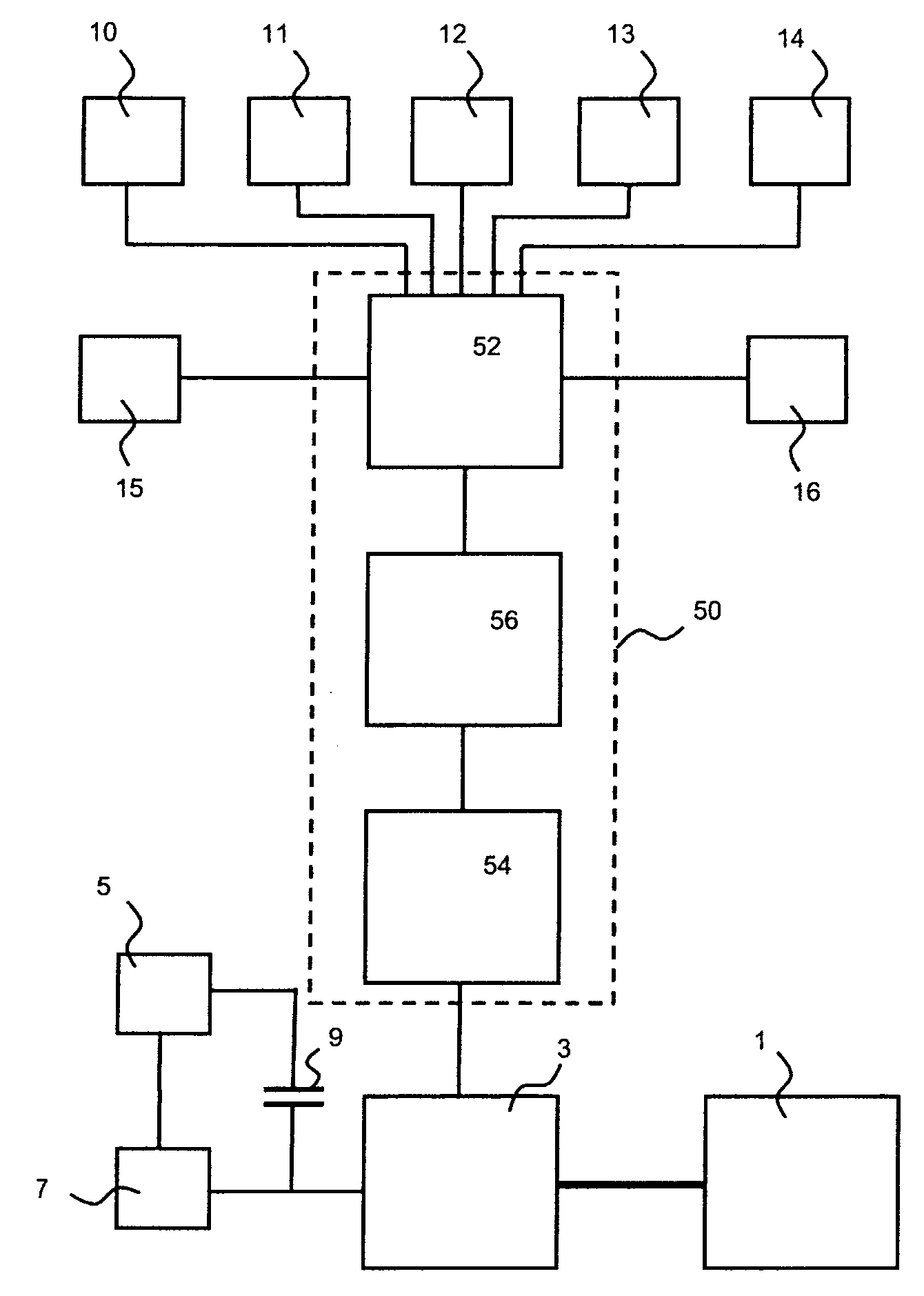
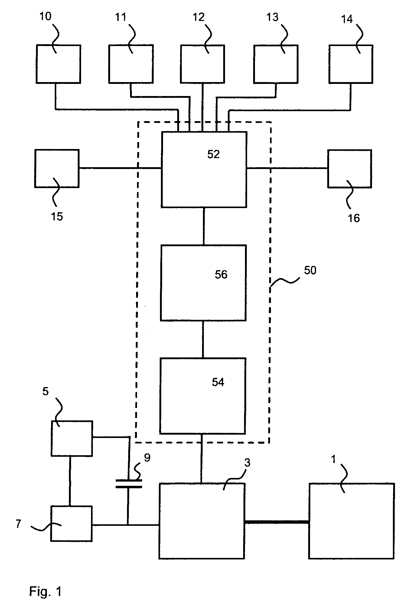
[0023]FIG. 1 shows in a schematic block circuit diagram components of a vehicle in conjunction with a brake device according to the invention. Only elements of the vehicle which are necessary to explain the brake device are illustrated for the sake of clarity. However, the vehicle can of course also have any other components which are usually present in vehicles.

[0024] The vehicle is equipped with a vehicle engine 1 which may be embodied, in particular, as an internal combustion engine, for driving the vehicle. In order to convert part of the engine power into electrical power, the vehicle also has a vehicle generator 3. In the present exemplary refinement, the latter comprises a magnetic rotor which is mechanically coupled to the engine 1 and an inductor which surrounds the rotor and has a coil winding. The mechanical coupling of the rotor to the vehicle engine, which can be brought about using, for example, a shaft, has the purpose of transmitting the rotary movement made availab...


PUM


Abstract

An inventive method for braking a vehicle when traveling on a negative gradient, which vehicle is equipped with a vehicle engine and a controllable vehicle generator which is connected to the vehicle engine in order to convert some of the engine power into electrical power.

Description

[0001] The present invention relates to a method for braking a vehicle when traveling on negative gradients, which vehicle is equipped with a vehicle engine and a controllable vehicle generator which is connected to the vehicle engine in order to convert some of the engine power into electrical power. Furthermore, the invention relates to a brake device and to a vehicle which is equipped with a brake device. BACKGROUND [0002] Devices for braking are standard equipment in a large number of vehicles nowadays. For example, in motor vehicles, what are referred to as permanent brake systems are known. The “handbrake or parking braking system” of a motor vehicle is taken to refer to the permanent braking system of the vehicle, that is typically actuated when the vehicle has come to a permanent stop, for example when the vehicle is parked. Alternatively, the permanent braking system may be employed while waiting at traffic lights. Therefore, a “permanent stop” is defined herein as a stoppa...

Claims


Application Information

Patent Timeline
IPC IPC(8): G06F19/00
CPCB60T1/10B60T13/586
Inventor LEYTEN, MAXEIFERT, MARK
Owner FORD GLOBAL TECH LLC
Learn More