
Apparatus and method for using a backshell

a backshell and apparatus technology, applied in the direction of electrical apparatus, coupling device connection, support structure mounting, etc., can solve the problems of mechanical connection failure, permanent interruption of signals being transmitted, distorting or destroying signal integrity, etc., and achieve the effect of strong mechanical connection

Inactive Publication Date: 2003-05-13
HONEYWELL INT INC
View PDF15 Cites 14 Cited by
  • Summary
  • Abstract
  • Description
  • Claims
  • Application Information

AI Technical Summary

Benefits of technology

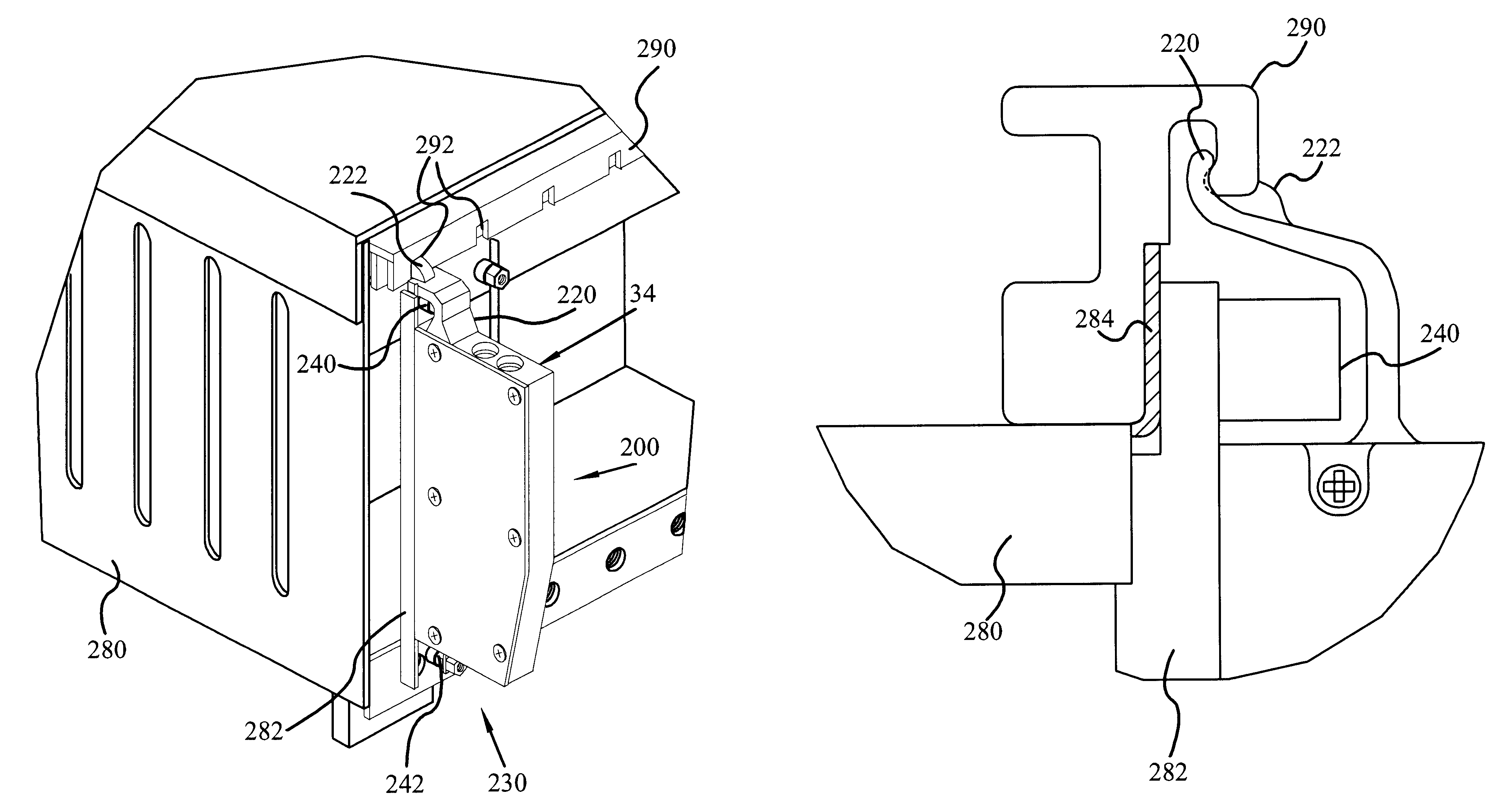
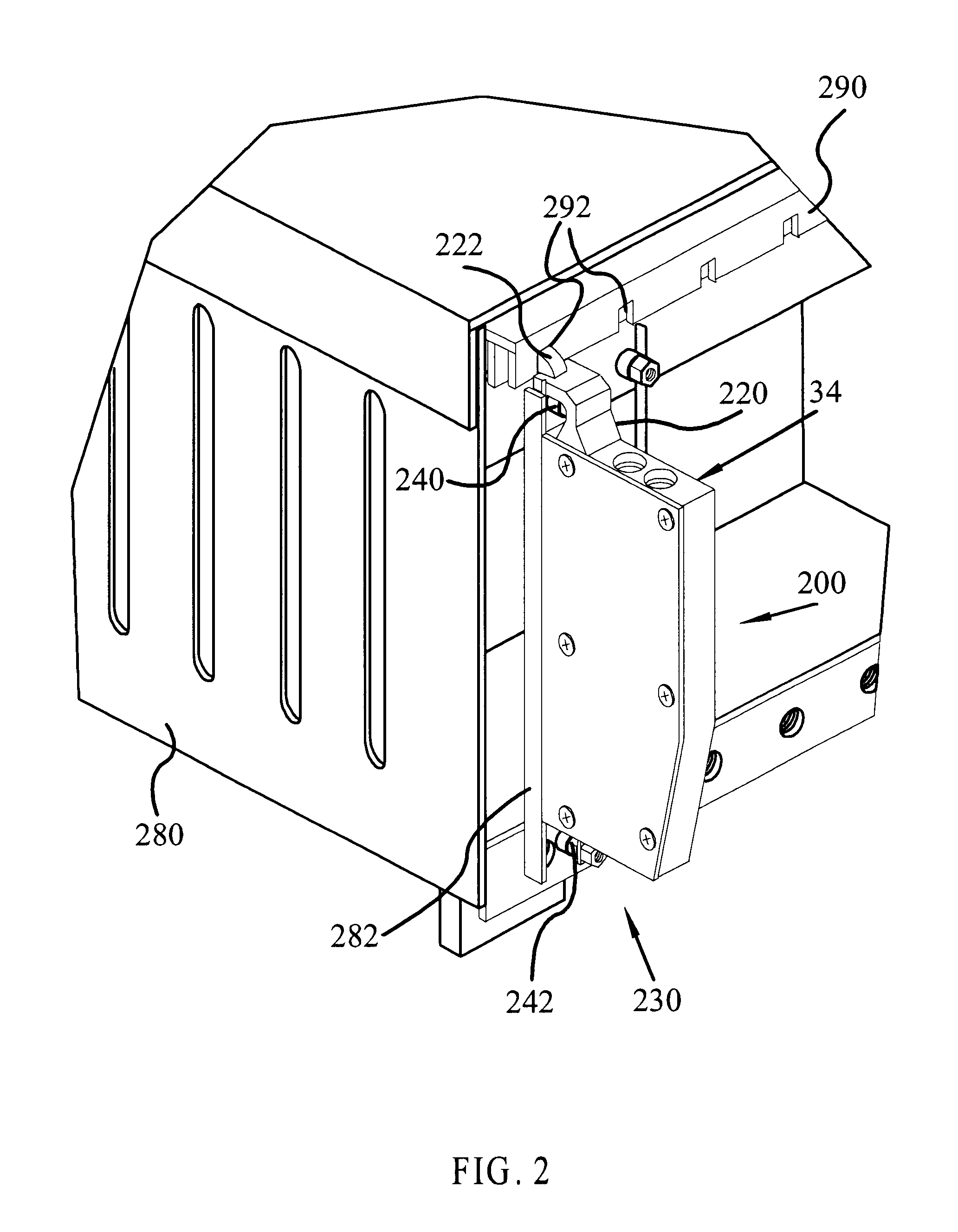
In an exemplary embodiment, a back shell is provided for forming an electrical connection with a cabinet, the backshell comprising at least one electrical connector, such as a D subminiature connector, a deflection arm coupled to one end of the back shell for engaging a cam on a cabinet which holds a receiving connector, and a fastener, for example, a captive mechanical jackscrew, on the opposite end of the backshell from the deflection arm. The deflection arm provides a clamping force when the fastener is fully engaged, and helps form a strong mechanical connection. In another exemplary embodiment, a mechanical jackscrew is provided on both ends of the backshell for securing the backshell to the cabinet.

Problems solved by technology

While this sort of connection may be sufficient in some applications, a large number of situations exist where the environment provides particularly challenging conditions which may cause the mechanical connection to fail.
The failures may be a permanent disconnection of the wires resulting in a permanent interruption in the signals being transmitted or communicated, or may be temporary or intermittent open circuits which distort or destroy the signal integrity.
In many applications, even a momentary disruption in signal integrity can have very undesirable results.
Electrical connections which are made between avionics devices are often subject to a rigorous vibrational environment.
Also, the small No. 4 size screws 40 can slip and fail to maintain the connection under rigorous environmental conditions.
Furthermore, the vibrations may cause the connection point between the wires of the device and the wires in the backshell to disengage unless constant pressure keeps the wires held together.
Although the present discussion focuses primarily on the rigorous vibrational environments found in fixed-wing aircraft and helicopters, similarly challenging environments may be found in pumps, fans, motors, and other large machinery found, for example, on oil rigs, shop floors, and other such high vibration applications.
Furthermore, connections between cable bundles and electrical devices may be challenged by other environmental factors such as high temperatures, or large temperature changes, low and high humidity conditions and electromagnetic radiation environments.
These D subminiature connectors, when attached by methods of the prior art, may not be mechanically robust and may lack the ability to provide a reliable signal.
Furthermore, the prior art D subminiature type connectors are bulky, often difficult to install, and lack packaging efficiency.
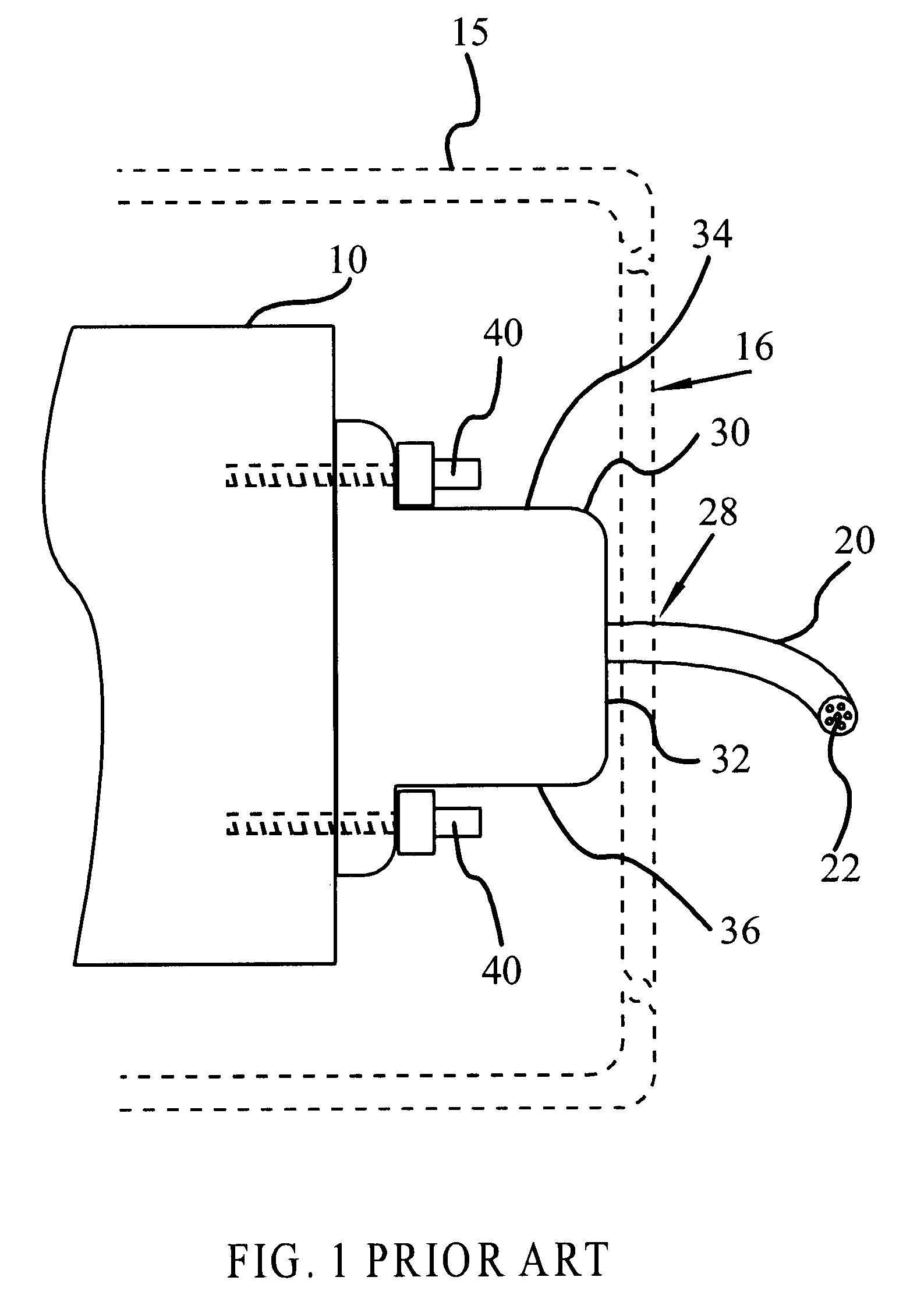
One difficulty that has been encountered with the use of the D subminiature connectors is that cabinet 15 (such as the cabinet illustrated in FIG. 1) which contains one or more devices 10 is typically very small and leaves little room for accessing the thumb screws 40.
Moreover, standard backshells are a difficult fit in congested avionics bays.
When these connections are in line and close together, it is harder still to obtain access to the mechanical fasteners.
Moreover, the screws 40 used to attach standard D subminiature connectors are limited to the small No. 4 size screws that fit into standard D subminiature threaded screw receiving holes in the mating D subminiature connector.
Therefore, it has been difficult to provide a means of mating the D subminiature connector with any other fastener other than these small screws, and it has thus been difficult to form a connection which can withstand the rigorous vibration environments found in aircraft avionics bays.

Method used


Image

  • Apparatus and method for using a backshell
  • Apparatus and method for using a backshell
  • Apparatus and method for using a backshell

Examples


Embodiment Construction

An apparatus and method for using the apparatus in accordance with various aspects of the present invention provide an improved electrical signal connection for avionics related backshells. In this regard, the present invention may be described herein in terms of functional block components and various processing steps. It should be appreciated that such functional blocks may be realized by any number of components configured to perform the specified functions. For example, the present invention may employ various magnetic radiation grounding techniques, such as Deutsch grounding blocks, lug terminations, Tag Rings, and the like. Tag Ring is a brand name for a 360 degree EMI shield produced by Glenair. Furthermore, a variety of mechanical fasteners may be used to secure a backshell to a cabinet. Such general components that are known to those skilled in the art are not described in detail herein. It should further be understood that the exemplary process or processes illustrated may...


PUM


Abstract

A backshell for forming an electrical connection with a cabinet, the backshell including at least one electrical connector, a deflection arm coupled to one end of the backshell for engaging a cam on a cabinet which holds a receiving connector, and a fastener on the opposite end of the backshell from the deflection arm. The deflection arm provides a clamping force when the fastener is fully engaged, and helps form a strong mechanical connection.

Description

1. Technical FieldThe present invention relates generally to electronic signal connectors and, more particularly, to a backshell configuration for providing a mechanical connection for communicating signals in a rigorous vibration environment.2. Background InformationElectrical connections are commonly used in transmitting signals and data between computers, systems and other devices. Typically, one device is connected to another device or system through a single wire or multiple wires. In many instances, a cable bundle containing these wires terminates in a mechanical housing, also known as a backshell, which provides physical protection for each wire in the cable bundle to each pin in an apparatus for making mated connections in the connected device. A backshell also protects the wires and connectors from fatigue. For example, FIG. 1 shows a typical prior art connection between a device 10 and a cable bundle 20 containing multiple wires 22. The cable bundle 20 terminates in a mech...

Claims


Application Information

Patent Timeline
Patent Type & Authority Patents(United States)
IPC IPC(8): H01R13/639H05K7/14H01R13/621H01R13/627
CPCH05K7/1452H01R13/6395H01R13/6215H01R13/6272H01R12/7005
Inventor HIRSCHBERG, ROBERT N.BAERMAN, ROGER A.BODLE, JOHN W.EDDY, BRETT A.OVERMAN, ROB
Owner HONEYWELL INT INC
Learn More