
Coated cloth with printed pattern

Inactive Publication Date: 2003-05-13
CAMO TEK
View PDF23 Cites 5 Cited by
  • Summary
  • Abstract
  • Description
  • Claims
  • Application Information

AI Technical Summary

Benefits of technology

The present invention provides such a coating that does not detract from the appearance of the pattern. Moreover, the coating surprisingly enhances the appearance of the pattern. This is particularly true when the coating is applied to fabric having three-dimensional camouflage patterns--the coating layer enhances the appearance of the printed pattern and adds a three-dimensional clarity to the printed pattern that is not present without the coating layer. Thus the coating enhances the disguising effect of camouflage patterned fabric.
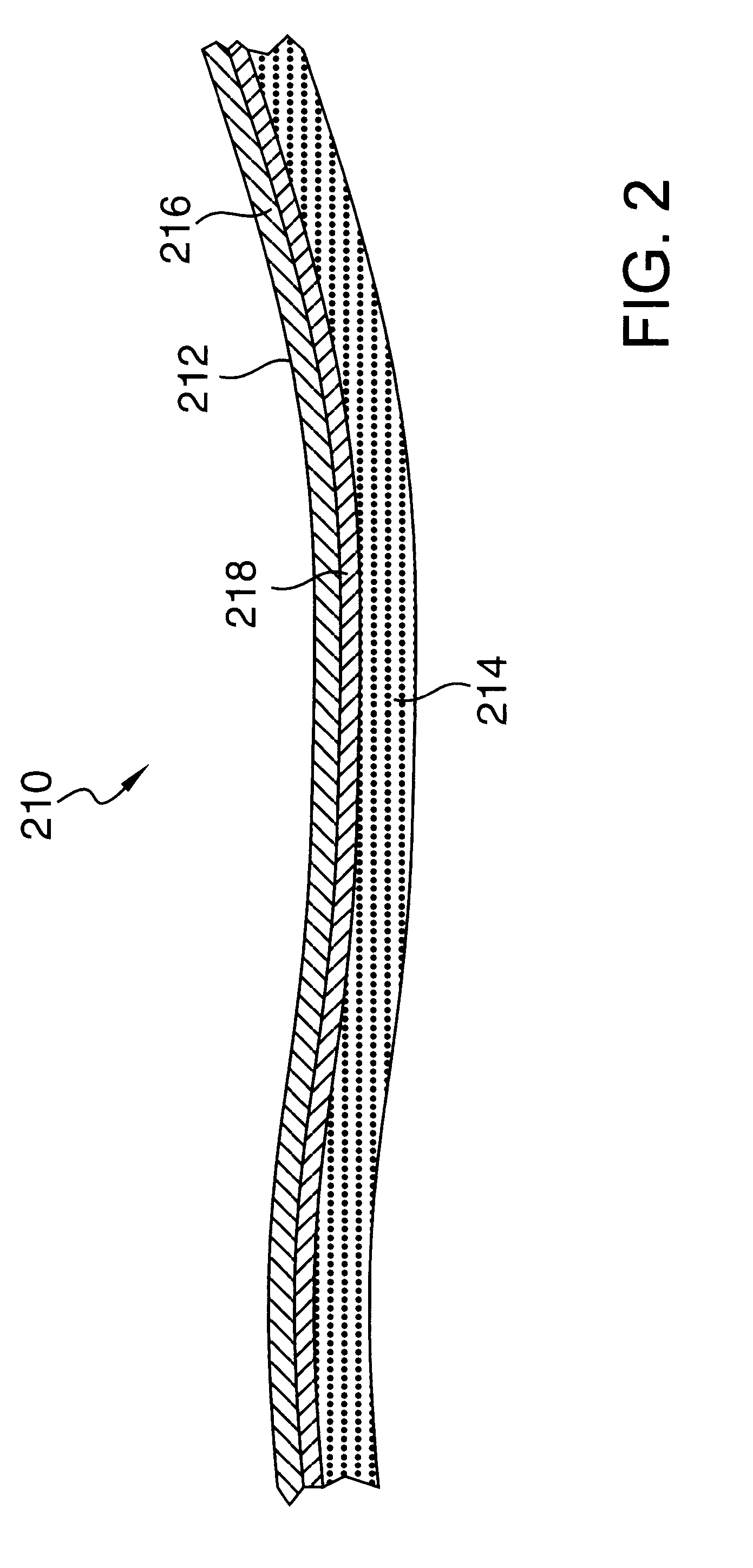
According to the present invention, a coated cloth includes a fabric layer having a three-dimensional pattern printed thereon. A clear coating layer is secured to the fabric layer and disposed over at least a portion of the three-dimensional pattern. Such an abrasion resistance is sufficient so that the appearance of the coating layer will not be damaged during normal use, and particularly during outdoor use.
The present invention also includes a method of forming a coated cloth. The method includes applying a coating material to a substrate, thereby forming a coating layer on the substrate. The coating layer is allowed to partially cure, and a three-dimensionally patterned fabric layer is applied to the coating layer. The coating layer is allowed to fully cure so that the coating layer is clear. The method may also include applying an adhesive material to the coating layer, thereby forming an adhesive layer that bonds the fabric layer to the coating layer. The adhesive layer will typically allow the coating layer to be cured at lower temperatures without reducing the clarity of the coating layer. Also, multiple colors may be printed on the fabric layer by screen printing.

Problems solved by technology

It is typically desirable for the coating layer to have a dull finish because a shiny finish would alter the appearance of the pattern and would likely thwart the disguising function of the pattern if the pattern is camouflage.

Method used


Image

  • Coated cloth with printed pattern
  • Coated cloth with printed pattern
  • Coated cloth with printed pattern

Examples


Embodiment Construction

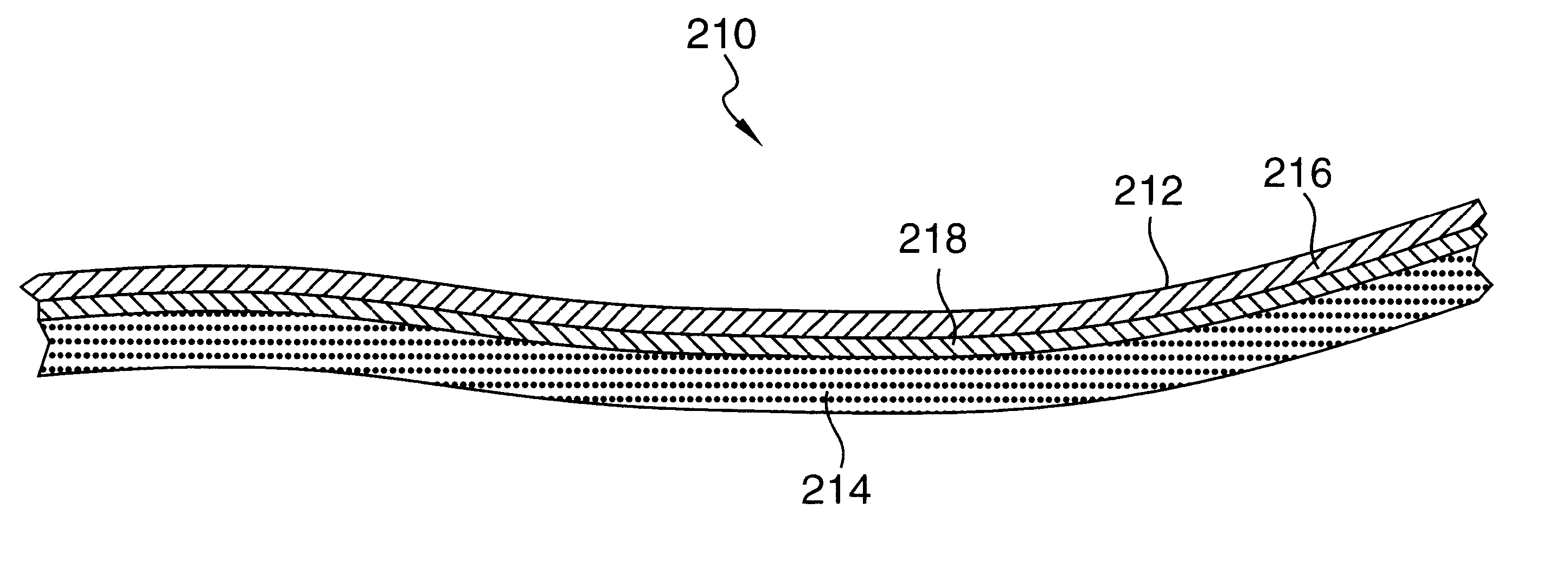
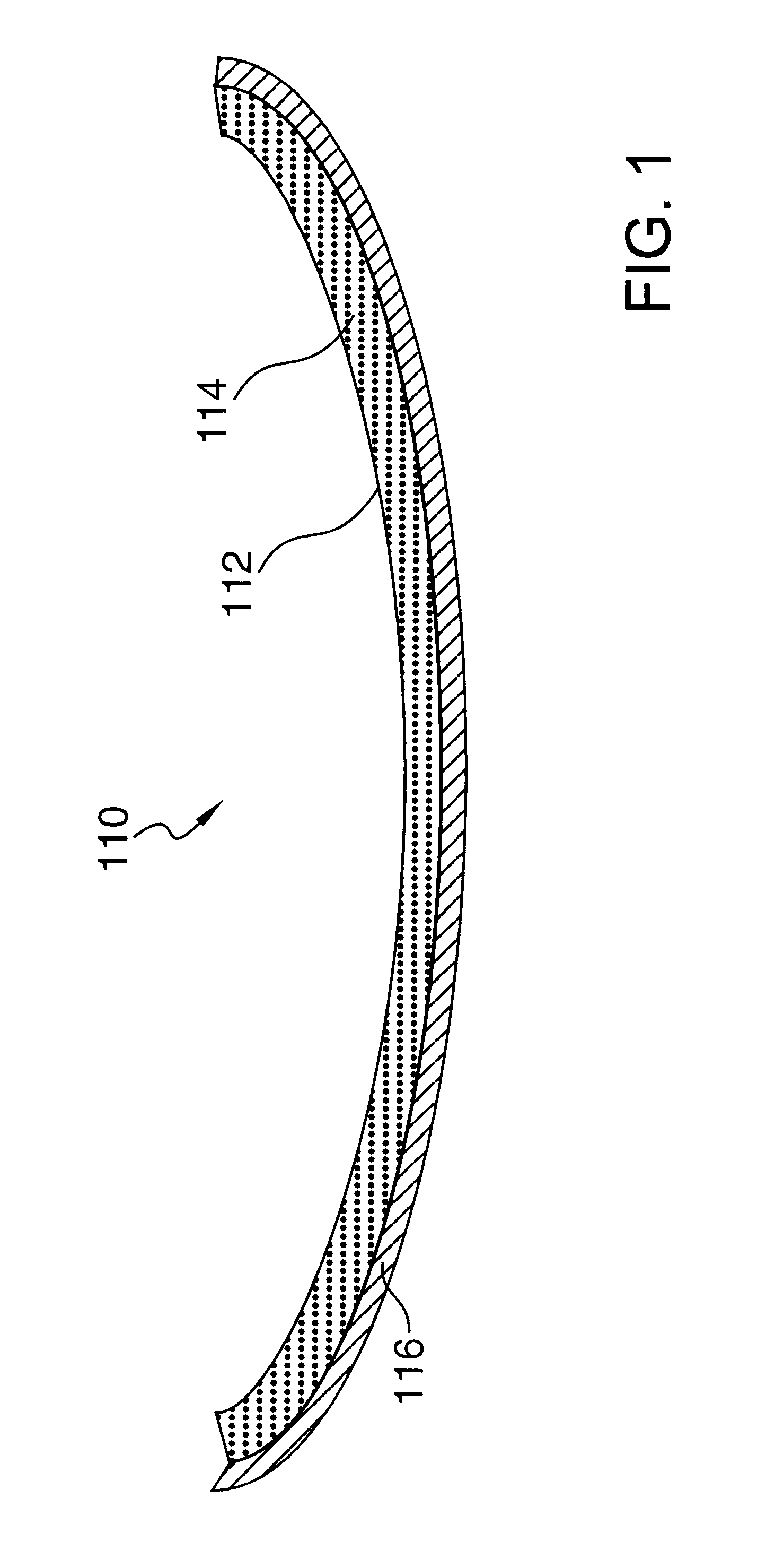
Referring to FIG. 1, in an embodiment of the present invention, a portion of a glove 110 includes an outer layer that is a coated cloth 112. It should be noted that all of cloth 112 may be coated or only a portion of cloth 112 may be coated. Coated cloth 112 includes a fabric layer 114 and a coating layer 116 secured to fabric layer 114 and disposed over at least a portion of fabric layer 114. Fabric layer 114 is preferably secured to coating layer 116 by coating layer 116 penetrating the surface of fabric layer 114. Coating layer 116 is preferably clear, abrasion-resistant, and tacky or grippy. Fabric layer 114 preferably has a pattern printed thereon, which is preferably a three-dimensional camouflage pattern.

Coating layer 116 provides abrasion protection for fabric layer 114. Coating layer 116 also provides a tacky or grippy surface that enhances the wearer's grip when such a wearer uses the gloves to grip objects. Coating layer 116 also enhances the appearance of the printed pat...


PUM

PropertyMeasurementUnit
Lengthaaaaaaaaaa
Thicknessaaaaaaaaaa
Massaaaaaaaaaa

Abstract

A coated cloth includes a fabric layer having a three-dimensional pattern printed thereon. A clear coating layer is secured to the fabric layer and disposed over at least a portion of the three-dimensional pattern. Also, the cloth may include a clear adhesive layer forming a bond between the coating layer and the fabric layer. The present invention also includes a method of forming a coated cloth. The method includes applying a coating material to a substrate, thereby forming a coating layer on the substrate. The coating layer is allowed to partially cure, and a three-dimensionally patterned fabric layer is applied to the coating layer. The method may also include applying an adhesive material to the coating layer, thereby forming an adhesive layer that bonds the fabric layer to the coating layer.

Description

1. Technical FieldThis invention relates to a coated cloth, and more specifically to a cloth having a three-dimensional or camouflage pattern printed thereon.2. Background ArtMany types of patterns have been printed on fabric. Camouflage patterns are commonly printed on fabric to disguise the fabric, and thus the wearer or contents of the fabric. Different camouflage patterns are used to disguise the fabric for different types of terrain. For example, the camouflage pattern may be made to appear like a tree. Such camouflage may include a pattern that depicts leaves, tree bark, and branches.Camouflage patterns are typically three-dimensional patterns (meaning that they appear to have depth). The three-dimensional appearance of the patterns is important because a two-dimensional appearance will make the fabric stand out in comparison to a real three-dimensional object such as a tree. It is also important that the particular colors of each pattern, including tones, hues and shading are...

Claims


Application Information

Patent Timeline
IPC IPC(8): D06N3/00D06N7/00F41H3/00F41H3/02
CPCD06N3/0059F41H3/02D06N7/0092Y10S428/919Y10S2/90D06N2211/10Y10T428/24818D06N2209/105D06N2209/083Y10T428/24364Y10T428/2481Y10T428/24802Y10T428/24355D06N2209/128Y10T442/2525Y10T442/2738Y10T442/444Y10T442/40Y10T442/273B32B27/12
Inventor CORRELL, RODERICK W.DINATALE, CHARLES J.ARNOLD, RICHARD B.LUBIN, PAUL M.
Owner CAMO TEK
Learn More