
Small footprint power transformer incorporating improved heat dissipation means

a technology of heat dissipation means and small footprint, which is applied in the direction of transformer/inductance cooling, electrical equipment, basic electric elements, etc., can solve the problems of increased losses, increased weight of windings, and inefficient ducts

Inactive Publication Date: 2003-05-13
MARTON LOUIS L
View PDF1 Cites 37 Cited by
  • Summary
  • Abstract
  • Description
  • Claims
  • Application Information

AI Technical Summary

Problems solved by technology

These ducts are not very efficient, because the cooling medium moves slowly in narrow spaces, and warms up considerably before finally exits at the top of the duct.
Thus the weight of the winding also increases, and the losses.
Using longer core legs and longer windings to increase the cooling surface, but the losses further increase.
Deviating the configuration more from the optimum format, the toroid--which has the minimum material content, but inferior cooling surfaces for natural convection creates this increase.
Generally, a large part of the gain expected from enlarging the cooling surfaces of the winding is canceled by increased weight and losses.
This patent, however, limits the use of heat dissipators to tubular layer-wound winding structures mounted on vertical core legs.
These units are still in flawless operation.
This small scale production has been discontinued only because of lack of interest in energy saving, lack of honest cooperation between partners, unfair competition, and lack of adequate working capital.
In 1980, the Department of Energy still refused to offer meaningful support.
Thus, in the past twenty-five years, the substantial improvements introduced by this technology remain unused.
Some of the drawbacks emerge in the production.
Winding tightly is a slow process.
This flux orientation makes heat dissipator application very difficult when the winding is built up from discs.
To prevent this problem by splitting up the inserted portion of the dissipator into narrow sections, the tooling becomes prohibitively expensive, and the assembly gets complicated.
Furthermore, the method described in the prior art cannot be used with dissipators having longer fins.
Thus, the application of heat dissipators in tubular windings built up from discs is limited to short fins, usable only in liquid cooling.
Considering the expensive tooling costs and the additional labor costs this version requires, dissipator cooling for discs in tubular winding systems is not economical.
Further drawbacks in layer wound windings become apparent after removing the completed winding from the winding machine.
The combined work of tight winding, dissipator implantation, and the subsequent cutting and bending operations of the dissipators require additional skilled labor time and extra care.
Due to the uneven hand-cutting of the bent louver-like structure, the finished transformers don't have a smooth professional appearance.
This aspect tends to diminish the acceptability of the product for some customers.
When during assembly or cleaning, the fin segments have been bent up and down three times, they have the tendency to break off.
After impregnation, there is no remedy possible.
When building transformers with higher kVA rating, the efficiency of the dissipator arrangement diminishes.
There is difficulty of accommodating more levels of louver-like structures crowding at both ends of the windings.
This solution leads to longer legs, thus heavier units andincreased losses.
Continuing the winding with the bent-up segments may cause injury to the fin segments, or to the winder.
In addition, the connections of the multiple segments of the windings become difficult to accommodate in the limited space left open by the fin segments.
Ultimately, these difficulties limit the size of the units that is economically feasible with dissipator-cooled layer-wound windings presented in the prior art.
This configuration coupled with close to square windows leads to smaller floor space requirement.
These discs can be produced using multiple winding techniques and saving labor time and production costs.
These disc coils can be multiple wound between flanges on the same machine, saving labor time.
Furthermore, heavy short circuits create significant forces between primary and secondary windings, and tend to push them apart; therefore the proper dimensioning of these parts is crucial.

Method used


Image

  • Small footprint power transformer incorporating improved heat dissipation means
  • Small footprint power transformer incorporating improved heat dissipation means
  • Small footprint power transformer incorporating improved heat dissipation means

Examples


Embodiment Construction

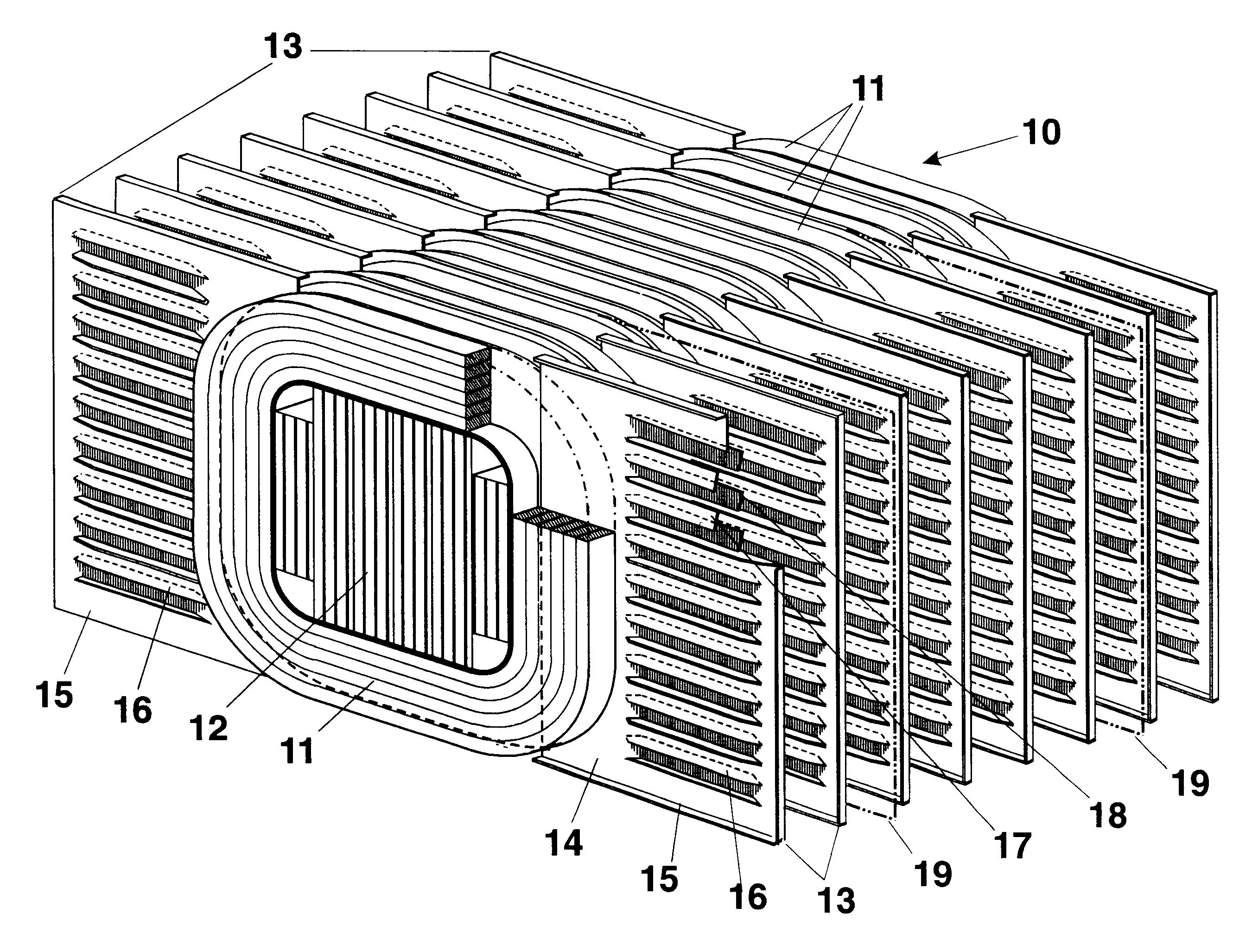
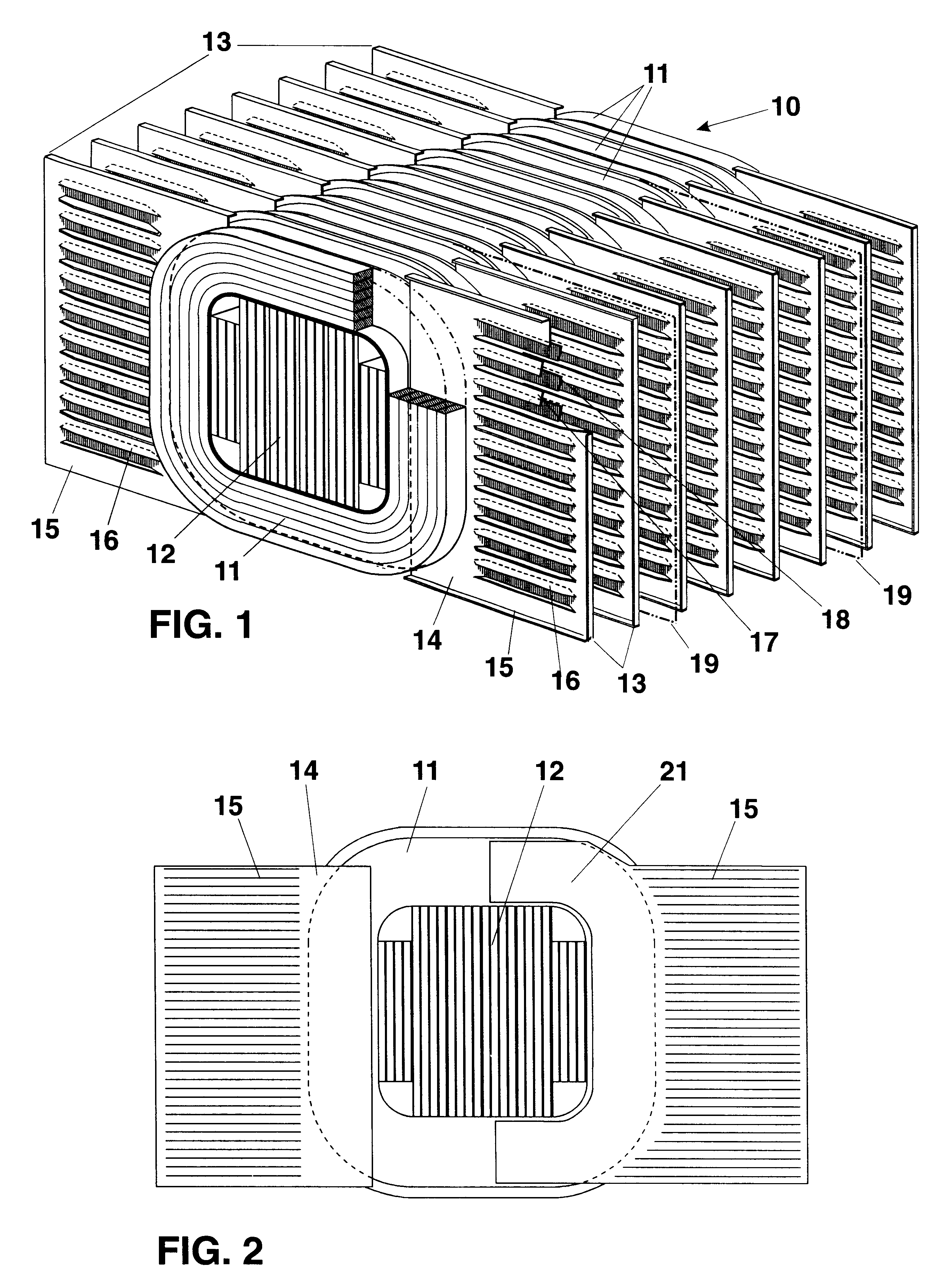
FIGS. 7 and 8 illustrate the shell type core structure used in FIGS. 5 and 6. The core 51 is constructed from building blocks e.g. 71, 72, 73, of steel lamination stacked to have equal height and assembled with butt joints. The wider leg blocks 71 and the end blocks 72, and the yoke blocks 73, 74 extend to the entire length of the leg. Two short filler blocks 75, 76 close the magnetic circuit. After each block is in place on the same level, tie sheets 77 placed over the assembled blocks to bridge all butt joints, and to serve as mechanical connection between the blocks. Filler sheets 78, 79 are placed between tie sheets on the same level to complete the magnetic circuit between them. At least the shorter blocks 73, 74 can be provided with adhesive means for converting them into solid objects to facilitate the assembly of the core.

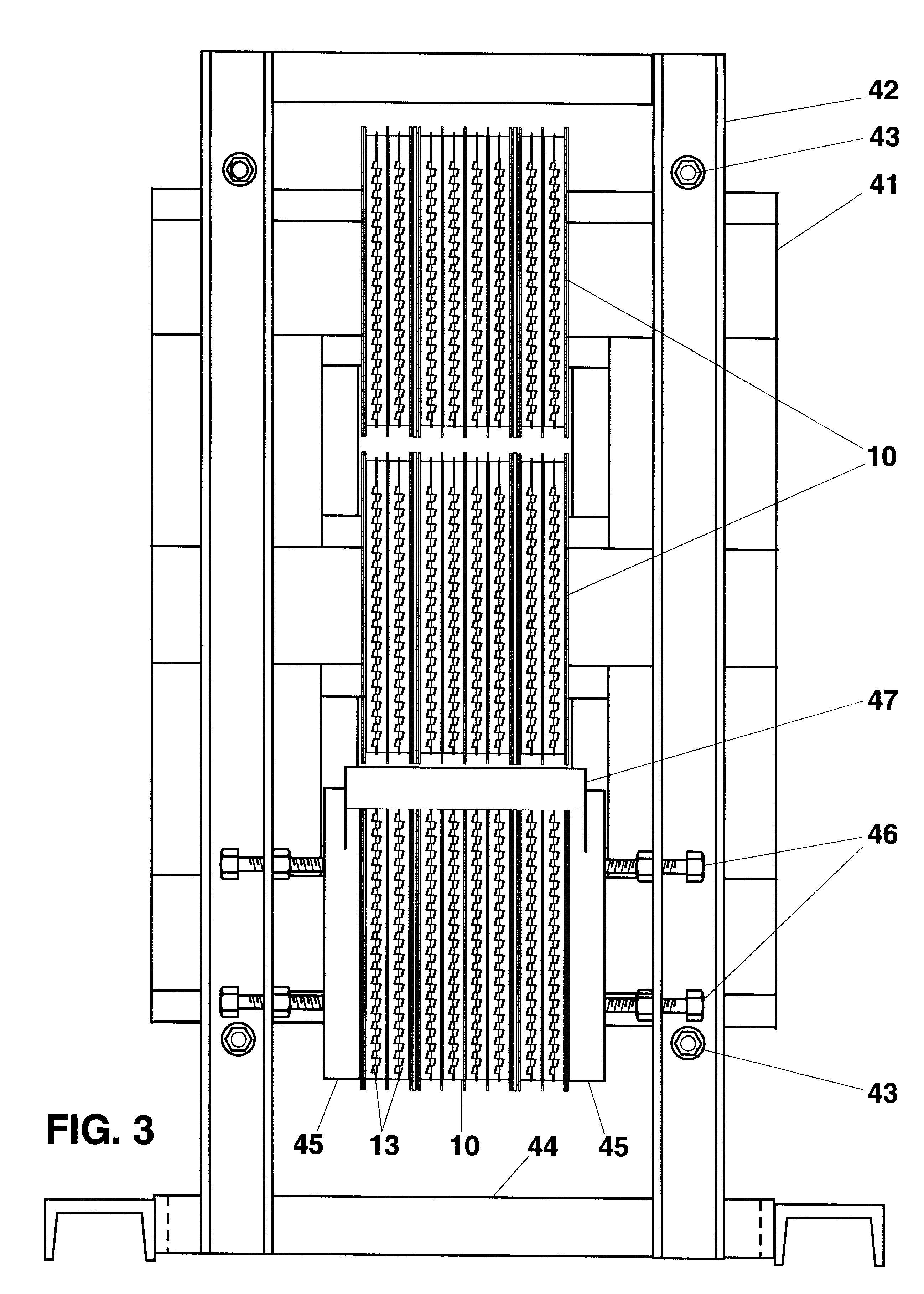
FIG. 9 illustrates a conventional three phase core 90 built in the same style as the core 51 in FIGS. 7, 8 and used in the transformer shown in FIGS. 3, an...


PUM


Abstract

A small footprint power transformer constructed so as to exhibit improved heat dissipation characteristics and an enhanced flow of a cooling medium. The transformer construction achieves small footprint by superimposing the core legs with the windings in vertical relationship. Highly heat conductive plane dissipators are inserted between adjacent finished coil discs and extended beyond the winding structure, terminating in fins arranged to assure maximum heat transfer to a cooling medium flowing therepast resulting in substantial reduction of the temperature rise.

Description

Not ApplicableBACKGROUND FIELD OF INVENTIONThis invention relates generally to small footprint transformers equipped with heat dissipators and, more particularly, to improved transformer constructions adapted to the more efficient cooling arrangements for dissipating heat generated in the winding structure of power transformers.BACKGROUND DISCUSSION OF PRIOR ARTTransformers, as most electric apparatus and equipment, do not have specific rating: their load carrying capacity is limited only by their temperature. In transformer windings, due to their resistance, losses are generated proportionally to the square of the load currents and eddy currents, warming up the windings. Their temperature, however, depends on the efficiency of the cooling arrangement used for removing the generated losses.In the present practice, natural convection plays the largest role in cooling via the surface of the winding. Tubular windings are in use almost exclusively. If the outside surface of the winding ...

Claims


Application Information

Patent Timeline
IPC IPC(8): H01F27/28H01F27/10
CPCH01F27/2876H01F27/10
Inventor MARTON, LOUIS L.
Owner MARTON LOUIS L
Features
  • Generate Ideas
  • Intellectual Property
  • Life Sciences
  • Materials
  • Tech Scout
  • Unparalleled Data Quality
  • Higher Quality Content
  • 60% Fewer Hallucinations
Learn More