
Frame for an electric scooter

a frame and electric scooter technology, applied in the field of frames, can solve the problems of uncomfortable steering of the steering bar and no shock-absorbing device for the front wheels of the conventional electric scooter,

Inactive Publication Date: 2003-05-20
LIN SAMUEL
View PDF7 Cites 17 Cited by
  • Summary
  • Abstract
  • Description
  • Claims
  • Application Information

AI Technical Summary

Benefits of technology

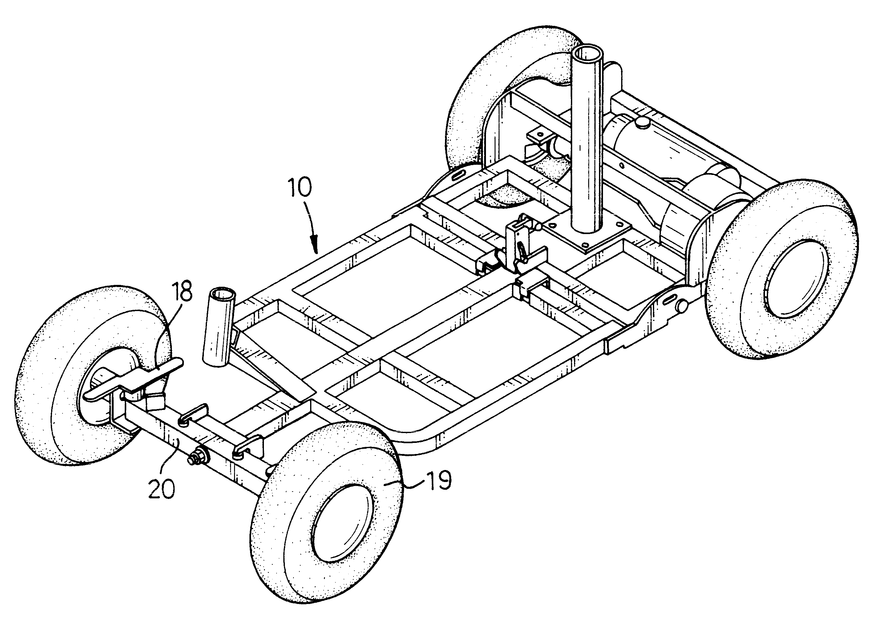
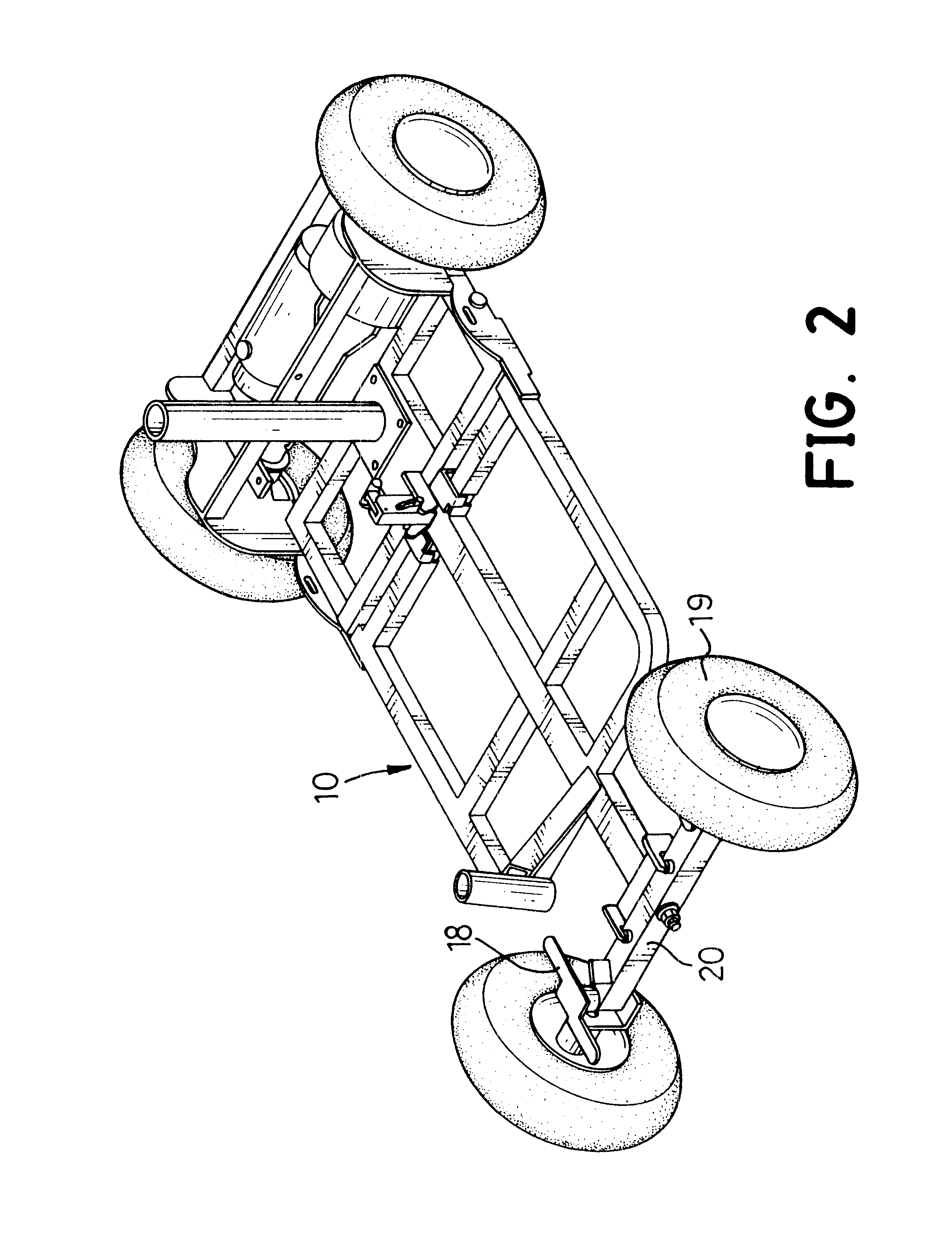
The pivotal bar (20) has a middle position and two ends and is pivotally attached to the lateral beam (12). A longitudinal through hole (202) is defined in the middle position of the pivotal bar (20) through which the pivot (122) extends. A nut (16) is screwed onto the pivot (122) and abuts the pivotal bar (20), such that the pivotal bar (20) is pivotally attached to the lateral beam (12) with the pivot (122) in cooperation with the nut (16). In addition, two bushings (17,172) are mounted in the through hole (202) in the pivotal bar (20) to reduce the friction between the pivot (122) and the inner surface of through hole (202) in the pivotal bar (20). The pivotal rotation of the pivotal bar (20) relative to the pivot (122) will be smoother.

Problems solved by technology

However, there is no shock-absorbing device for the front wheels of the conventional electric scooter.
To steer the steering bar and to drive the electric scooter are uncomfortable.

Method used


Image

  • Frame for an electric scooter
  • Frame for an electric scooter
  • Frame for an electric scooter

Examples


Embodiment Construction

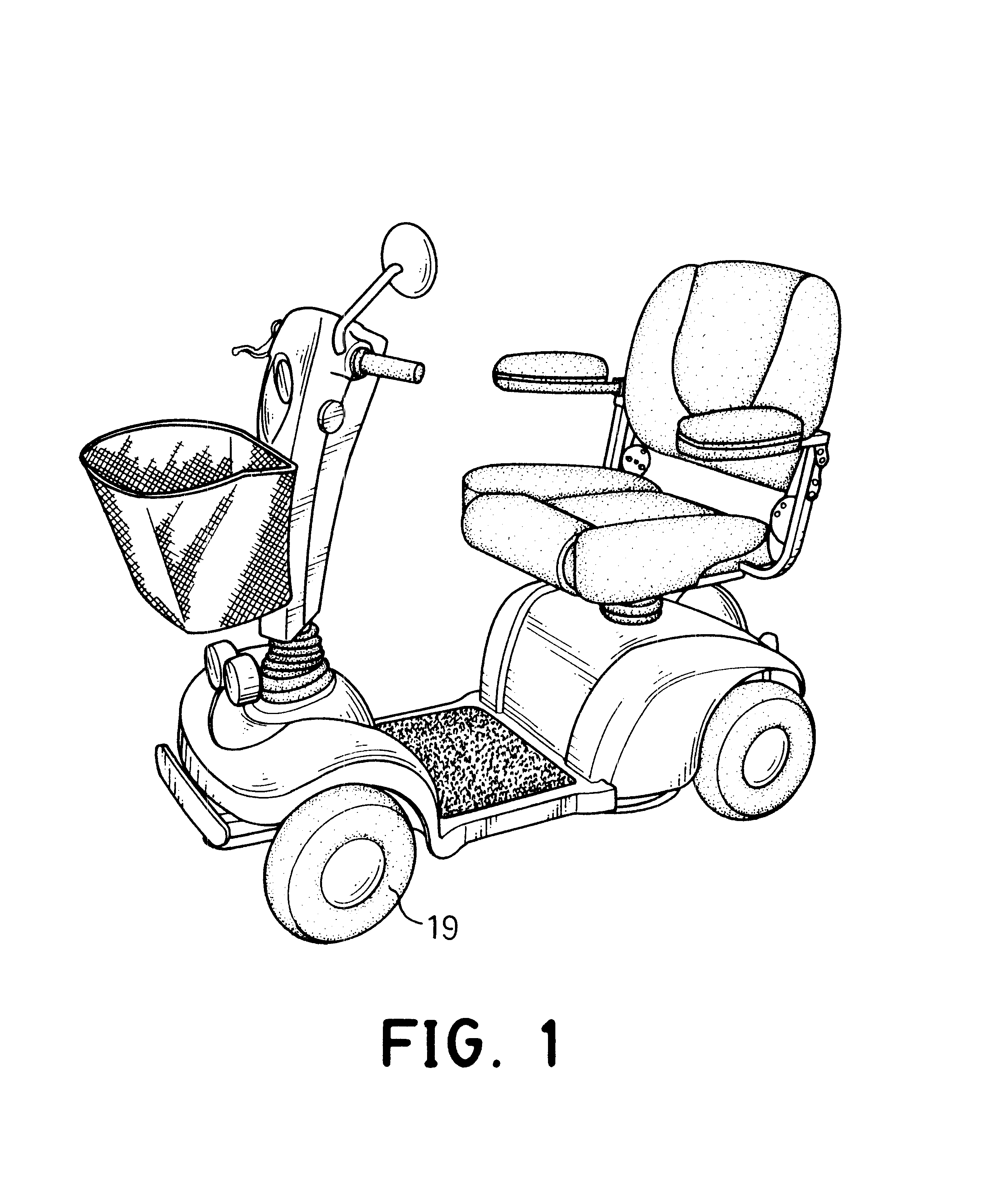
With reference to FIGS. 1 to 3, a frame for an electric scooter in accordance with the present invention comprises a body (10), two tabs (14), a pivotal bar (20), two wheel mounts (18) and two resilient members (24). The body (10) has a lateral beam (12) with a middle and two ends. The middle of the lateral beam (12) is attached to the front end of the body (10). A pivot (122) with an outer thread is securely attached to the middle position of the lateral beam (12) and extends from the front of the lateral beam (12). The two tabs (14) are respectively secured to opposite ends of the lateral beam (12).

The pivotal bar (20) has a middle position and two ends and is pivotally attached to the lateral beam (12). A longitudinal through hole (202) is defined in the middle position of the pivotal bar (20) through which the pivot (122) extends. A nut (16) is screwed onto the pivot (122) and abuts the pivotal bar (20), such that the pivotal bar (20) is pivotally attached to the lateral beam (1...


PUM


Abstract

A frame for an electric scooter has a body, a pivotal bar, two wheel mounts, two resilient members and two tabs. The pivotal bar is pivotally attached to the front end of the body. Each wheel mount is pivotally attached to one end of the pivotal bar in a longitudinal direction. A front wheel is rotatably attached to each of the wheel mounts. The resilient members are attached to the top of the pivotal bar. The tabs are secured to the body and respectively abut one of the resilient members. Consequently, one of the resilient members will be compressed when one of the front wheels is bumped. This can keep the force applied to the front wheel from being transmitted to the body and the steering bar of the scooter. To steer and to drive the electric scooter become is easier.

Description

1. Field of the InventionThe present invention relates to a frame, and more particularly to a frame with a shock-absorbing device for an electric scooter.2. Description of Related ArtAn electric scooter is used to help a person to move from place to place at a low speed. The conventional electric scooter substantially comprises a frame, two front wheels, two rear wheels, a seat, an electric motor and a steering bar. The front wheels are rotatably attached to the front end of the frame. The rear wheels are rotatably attached to the rear end of the frame. The seat is mounted on the frame for a user to sit. The electric motor is mounted on the frame to drive the rear wheels. The steering bar is pivotally mounted on the frame and is connected to the front wheels by a linking device, such that the direction in which the electric scooter travels is controlled by means of pivotally rotating the steering bar.However, there is no shock-absorbing device for the front wheels of the conventiona...

Claims


Application Information

Patent Timeline
Patent Type & Authority Patents(United States)
IPC IPC(8): B62K5/00B60G9/02
CPCB60G9/02B62K5/007B60G2200/322B60G2200/44B60G2204/4502B60G2300/12B60G2300/24B60G2204/45
Inventor LIN, SAMUEL
Owner LIN SAMUEL
Learn More