Low profile cable end connector

a low-profile, cable-end technology, applied in the direction of connection contact material, coupling device connection, electrical apparatus, etc., can solve the problems of increasing the lengthwise dimension, the lengthwise dimension is increased, and the cable-end connector production cost is increased, so as to achieve the effect of reducing the lengthwise dimension and low profil

Inactive Publication Date: 2003-06-03
HON HAI PRECISION IND CO LTD
View PDF6 Cites 28 Cited by
  • Summary
  • Abstract
  • Description
  • Claims
  • Application Information

AI Technical Summary

Benefits of technology

Another object is to provide a cable end connector having a low profile and a reduced lengthwise dimension.

Problems solved by technology

However, the cable end connector with such a design regarding the connection of the terminal 30' with the inner conductor 71 of the cable 70 cannot meet a higher operating frequency requirement, such as 6 GHz.
Furthermore, particularly referring to FIG. 9, the retainer 60' of the cable end connector has a pair of locking tabs 63', a pair of braiding crimps 65' and a strain relief 69' respectively engaging with different portions of the cable 70 and the shell 50', which results in an increased lengthwise dimension and increased production cost of the cable end connector.

Method used


Image

  • Low profile cable end connector
  • Low profile cable end connector
  • Low profile cable end connector

Examples


Embodiment Construction

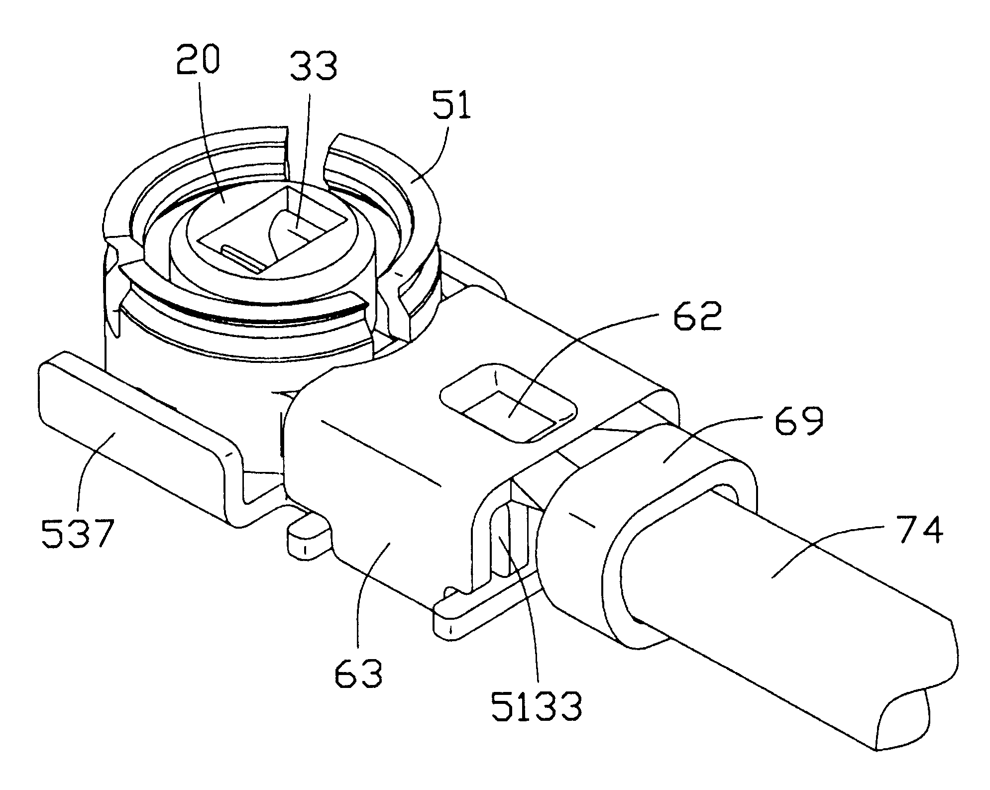
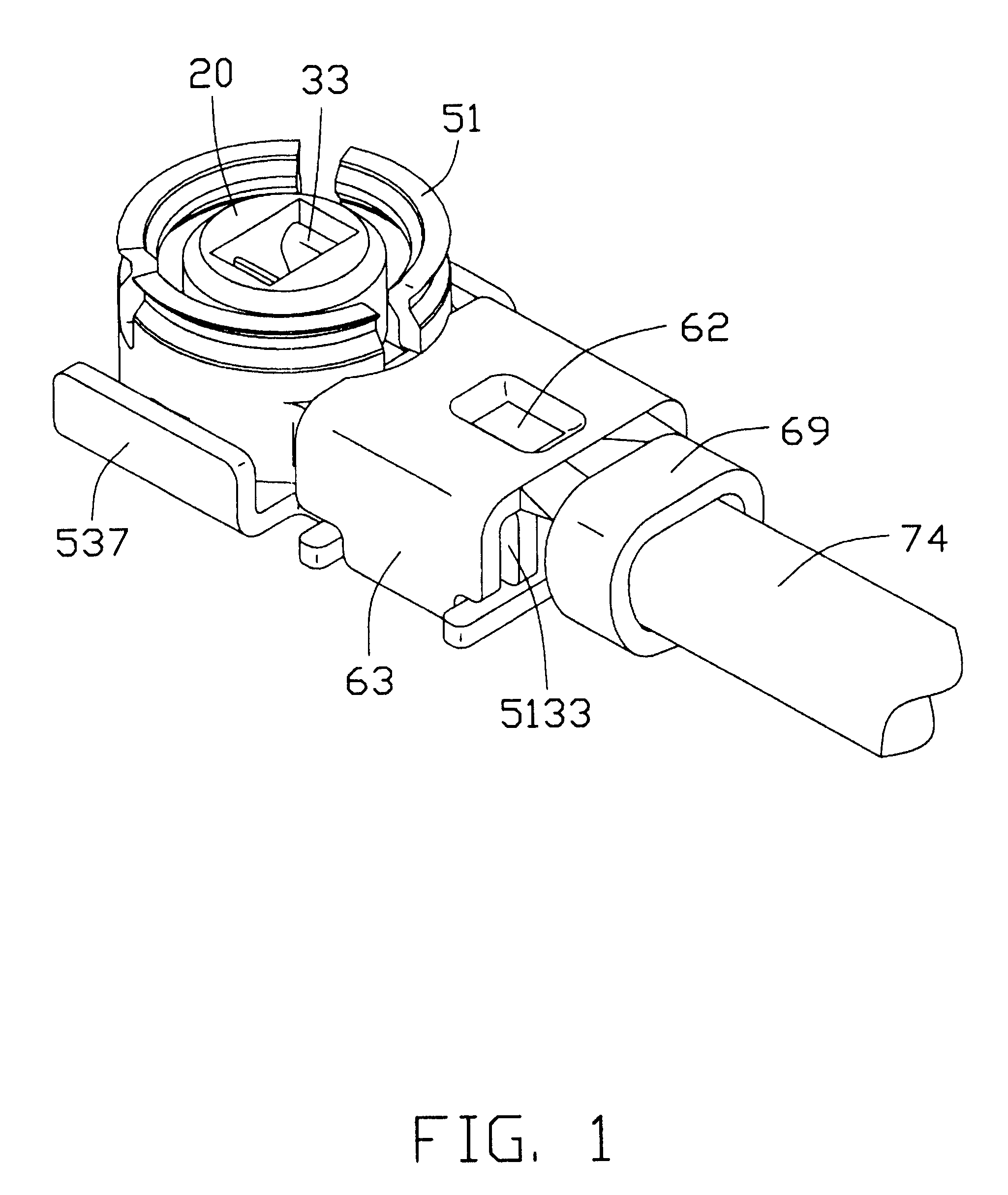
Referring to the drawings and particularly to FIGS. 1, 2, 4 and 5, a cable end connector in accordance with the present invention comprises a dielectric housing 10, a terminal 30, a metal shell 50 enclosing the housing 10 and the terminal 30, and a retainer 60 for securing an end portion of a coaxial cable 70 to the cable end connector.

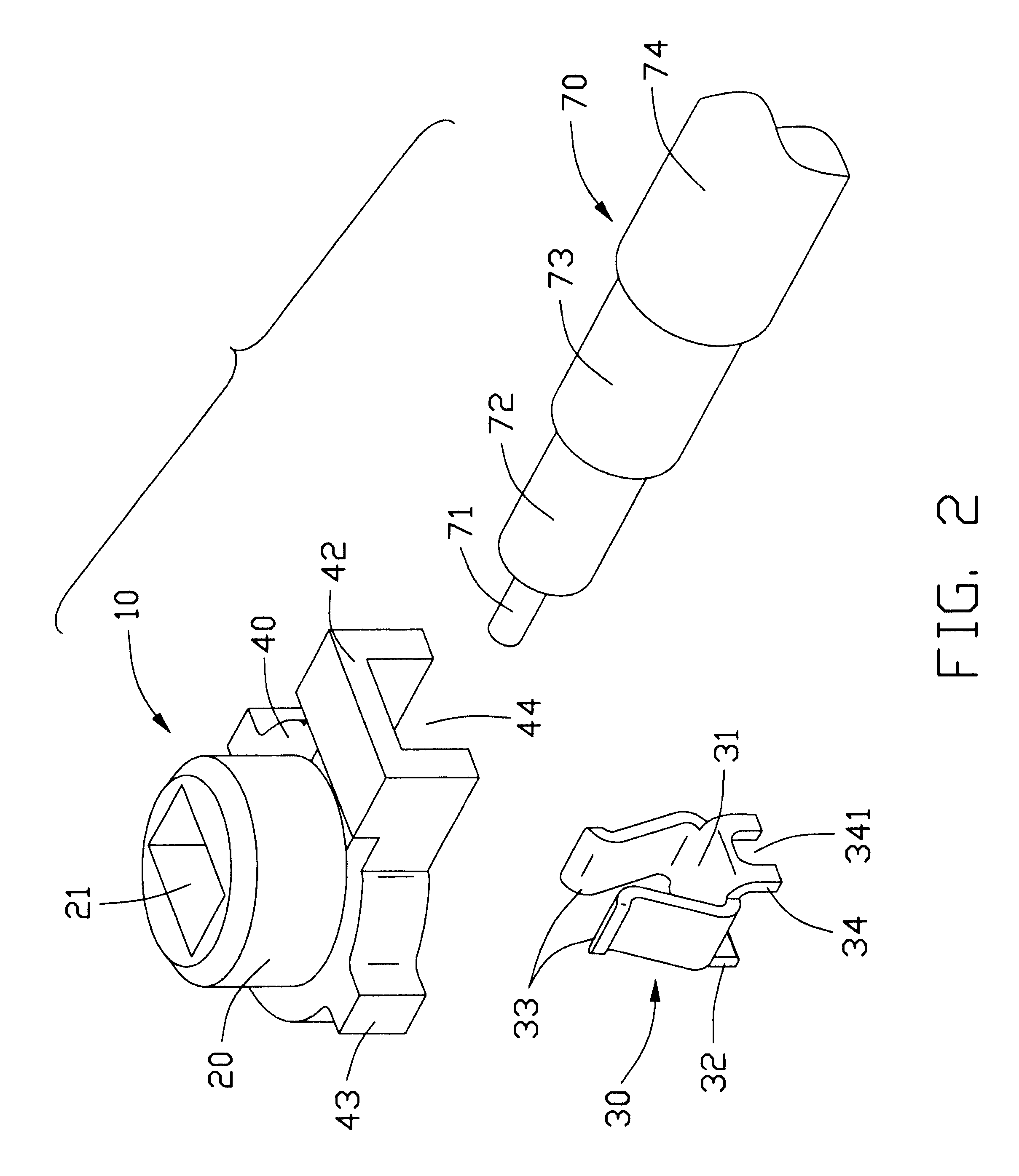
Particularly referring to FIG. 2, the dielectric housing 10 comprises a base portion 40 and a tubular portion 20 supported on the base portion 40. A substantially rectangular passageway 21 is axially defined through the tubular portion 20.

The terminal 30 includes a bottom portion 31 and a pair of mating wings 33 extending respectively and upwardly from two opposite lateral sides of the bottom portion 31. The pair of mating wings 33 substantially extend toward each other for mating with a mating terminal of a complementary connector (not shown). A first and a second soldering tabs 32, 34 are bent respectively and downwardly from two opposite longitudin...


PUM


Abstract

A cable end connector includes a dielectric housing (10), a terminal (30) received in the housing, a shell (50) enclosing the housing, and a retainer (60) attached to the shell for holding a coaxial cable (70) therein. An inner conductor (71) of the coaxial cable is directly soldered to a lower surface of a bottom portion (31) of the terminal. Two locking tabs (63) of the retainer achieves two functions: keeping integrity of the cable end connector and grounding a braiding layer (73) of the coaxial cable.

Description

BACKGROUND OF THE INVENTION1. Field of the InventionThe present invention relates to a connector, and more particularly to a low profile cable end connector for high frequency application.2. Description of the Related ArtAn RF (Radio Frequency) cable end connector is used for connecting a cable with an electronic device for transmitting RF signal. Such a conventional RF cable end connector is, for example, disclosed in U.S. Pat. Nos. 6,340,312 B1 and 6,305,980 B2. Both patents are invented by the same inventor of the present invention. Referring to FIGS. 8 and 9, which are similar to FIGS. 6 and 7 of the U.S. Pat. No. 6,340,312 patent, the cable end connector includes a dielectric housing 10', a terminal 30' received in the housing 10', a shell 50' enclosing the housing 10', and a retainer 60' attached to the shell 50' for holding a coaxial cable 70 therein. The terminal 30' includes a pair of mating portions 33' and a planar tail portion 31' extending rearwardly to contact with an ...

Claims


Application Information

Patent Timeline
Patent Type & Authority Patents(United States)
IPC IPC(8): H01R9/05
CPCH01R9/0518
Inventor KO, DAVID TSO-CHIN
Owner HON HAI PRECISION IND CO LTD
Why Eureka
Try Eureka